Encoders vs. Tachometers ???
- PCW
-

- Offline
- Moderator
-

- Posts: 17821
- Thank you received: 5213
Please Log in or Create an account to join the conversation.
- jCandlish
-
 Topic Author
- Offline
- Senior Member
-

- Posts: 77
- Thank you received: 4
No need, just use an encoder, better in every way
Great! Who has a donkey that deficates encoders?
Edit: and it isn't better in every way unless its negative logic. Otherwise a failure of the device leads to a runaway.
Please Log in or Create an account to join the conversation.
- cmorley
- Offline
- Moderator
-
- Posts: 7292
- Thank you received: 2130
First your machine should have a feedback device already somewhere (unless the drive is a step and direction servo).
The easiest would be to use it.
If the linear scale is the feedback device you can have tuning issues since the scale is not directly connected
to the motor.
next easiest would be to add a rotary encoder. which should work better then the linear scale.
The hardest would be trying to make a tach (a velocity sensor) act as an encoder (a position sensor)
And it is possible to have the PID control shutdown the motor if the encoder breaks
Peter has talked of this before. I believe it does it by counting how long the PID is saturated at maximum output
and if too long ( the servo is not keeping track ) it sets the output to zero.
You give very little detail of your situation to recommend much more.
Hope that helps
PS if rereading your post - I think you are stuck on trying to get the analog tach signal into linuxcnc via the 7i29.
What everyone is saying is you don't want the analog signal!
Please Log in or Create an account to join the conversation.
- jCandlish
-
Topic Author
- Offline
- Senior Member
-
- Posts: 77
- Thank you received: 4
hmm no need to beat us up for our advice.
The advice was taken in the nature it was given. 'Better in every way' is a remarkably bold assertion.
And it is possible to have the PID control shutdown the motor if the encoder breaks
Peter has talked of this before. I believe it does it by counting how long the PID is saturated at maximum output
and if too long ( the servo is not keeping track ) it sets the output to zero.
This is my next area of inquiry. How can I find out more about Servo-Loop fault conditions in EMC2?
Who is Peter?
You give very little detail of your situation to recommend much more.
Hope that helps
The information on PID control shutdown is new and helpful to me. I hope someone can follow up with more information about this.
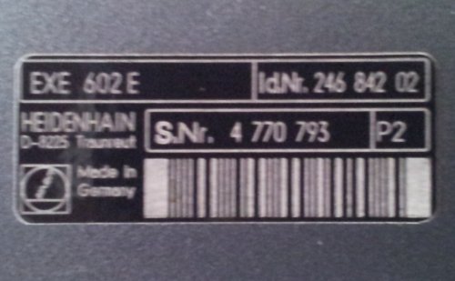
What additional information can I provide. I have ABB/IsoFlux 544 series Servomotors with integrated 0.02V/rpm tachometers. My goal is to drive these motors with 7i29 H-Bridges using EMC2 for control. My machine is also equiped with Heidenhain glass scales and EXE-602E resolvers, that I had thought to use in a secondary feedback loop.
PS if rereading your post - I think you are stuck on trying to get the analog tach signal into linuxcnc via the 7i29.
Not quite. I am stuck on using the existing analog tach signal with EMC2. Period.
What everyone is saying is you don't want the analog signal!
Agreed. But its what I have now to start with.
That both tachometer and encoder feedback are positive logic an therefore subject to runaway in a wire fault condition is troublesome to me. This is also a concern of mine in using the Heidenhain scales in a feedback loop, because they are not robust. I need to learn how EMC2 bounds feedback following errors.
Anyway does it really matter to EMC2 if the primary servo feedback is encoder derived (Radians) or tacho derived (dRadians/dT)?
Thanks for letting me think out loud.
_jC
.
Please Log in or Create an account to join the conversation.
- cmorley
- Offline
- Moderator
-
- Posts: 7292
- Thank you received: 2130
When I read 'resolver' I think of a feedback device sometimes found on ac servo motors.
So I am assuming that the original system used servo drives that used tach feedback and then used the scales as the positional feedback?
Or are you piecing this together your self?
Peter is the owner of Mesa electronics - he is PCW on this forum.
here is the docs for linuxcnc:
www.linuxcnc.org/docs/2.5/html/
look there and you will find info on the PID component ( and everything else )
There is a pin on it that counts how long the PID has been saturated. You could add logic to this to set an estop after a certain amount of time.
I think that is what Peter was talking of (it's been a while since that conversation)
Of course Linuxcnc will also fault if there is a (positional) following error beyond (user selectable) specifications
As it is linuxcnc expects positional feedback not velocity feedback.
You have been asking for the easiest way to make this work - and the easiest way is to add a rotary encoder or use the scales.
If you are determined to use the analog velocity signal and have linuxcnc convert it to a positional signal be prepared to buy more hardware,
do some programming and probably still not be happy with the results. What I am saying is while I think (not that I'm an expert) it might be possible it is certainly not practical.
Thinking out loud is a great way to flush out ideas!
Please Log in or Create an account to join the conversation.
- jCandlish
-
Topic Author
- Offline
- Senior Member
-
- Posts: 77
- Thank you received: 4
Yes.So I am assuming that the original system used servo drives that used tach feedback and then used the scales as the positional feedback?
Also, yesOr are you piecing this together your self?
As it is linuxcnc expects positional feedback not velocity feedback.
Is it EMC2 that expects this, or the 5i2x's FPGA?
Don't have emYou have been asking for the easiest way to make this work - and the easiest way is to add a rotary encoder
It will be interesting to see what happens in the drive belt failure error condition. PID tuning with only the scales must be very difficult.or use the scales.
If you are determined to use the analog velocity signal and have linuxcnc convert it to a positional signal be prepared to buy more hardware, do some programming and probably still not be happy with the results. What I am saying is while I think (not that I'm an expert) it might be possible it is certainly not practical.
I am determined to complete this conversion, and stand ready to take the necessary measures to do so.
Thinking out loud is a great way to flush out ideas!
Yeah, it helps greatly, and I thank this forum for the oportunity.
Rgds
_jC
.
Please Log in or Create an account to join the conversation.
- cmorley
- Offline
- Moderator
-
- Posts: 7292
- Thank you received: 2130
I guess to be truly accurate linuxcnc needs both position and velocity - it just calculate velocity from position.
Trying to calculate accurate position from approximate velocity and time seems about impossible.
Well if the drive belt breaks then the axis can't really crash (it can't move) so thats not that bad.
The motor would spin at maximum.
worse is when the feedback device fails - but it doesn't matter what type of feedback device, if it fails the motor is going to try to move faster.
It would seem success of tuning with scales would depend on how much lost motion (backlash) between motor and axis and the resolution of the scales.
Typically you get way more resolution with rotary encoders because of the gearing and leadscrew. your interpolator helps here though I believe the 602 is usually 5x (though it can be 1x - it should say on the box)
you say you are ready to take the necessary measures to make this work you have three practical options that I see.
buy servo drives that use tach feedback and use the scales for positional feedback ( you won't use the 7i29 to drive the motors )
buy some encoders and add them either to the motor or the leadscrew. (this is the probably best option)
use the scales as feedback (probably hard to tune right)
And thats the end of my opinion !
Hopefully I haven't told you any big lies
")
Chris M
Please Log in or Create an account to join the conversation.
- jCandlish
-
Topic Author
- Offline
- Senior Member
-
- Posts: 77
- Thank you received: 4
linuxcnc expects positional feedback ...
It would seem success of tuning with scales would depend on how much lost motion (backlash) between motor and axis and the resolution of the scales.
Typically you get way more resolution with rotary encoders because of the gearing and leadscrew. your interpolator helps here though I believe the 602 is usually 5x (though it can be 1x - it should say on the box)
The machine has 32x5mm ballscrews, with 2/1 belting giving 2.5mm/rev at the servos. The HH scales are 20um and interpolate to 4um *hopefully I've go the right 602 units. It doesn't say on the box. The HH documentation states that the 602 is adjustable, but I can find no documentation for the jumper blocks. Maybe someone here knows?
you say you are ready to take the necessary measures to make this work you have three practical options that I see.
buy servo drives that use tach feedback and use the scales for positional feedback ( you won't use the 7i29 to drive the motors )
buy some encoders and add them either to the motor or the leadscrew. (this is the probably best option)
use the scales as feedback (probably hard to tune right)
And thats the end of my opinion !
Hopefully I haven't told you any big lies
Chris M
I'll take whats behind door #2 Chris. Say, optical encoders are butt cheap. USDigital has these that could be made to fit:
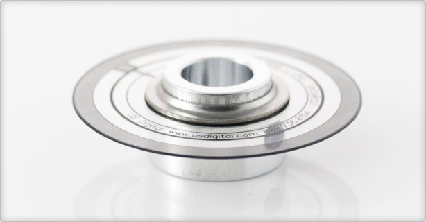
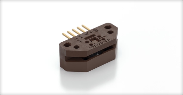
I would be interested to know of other suppliers as well.
With respect to interfacing the 7i29, the encoder connectors have pinouts for differential IDX,_IDX. I take it that those are optional.
Thanks again
John
.
Note to self: Don't try to post with the micron symbol.
Please Log in or Create an account to join the conversation.
- BigJohnT
-

- Offline
- Administrator
-

- Posts: 3990
- Thank you received: 994
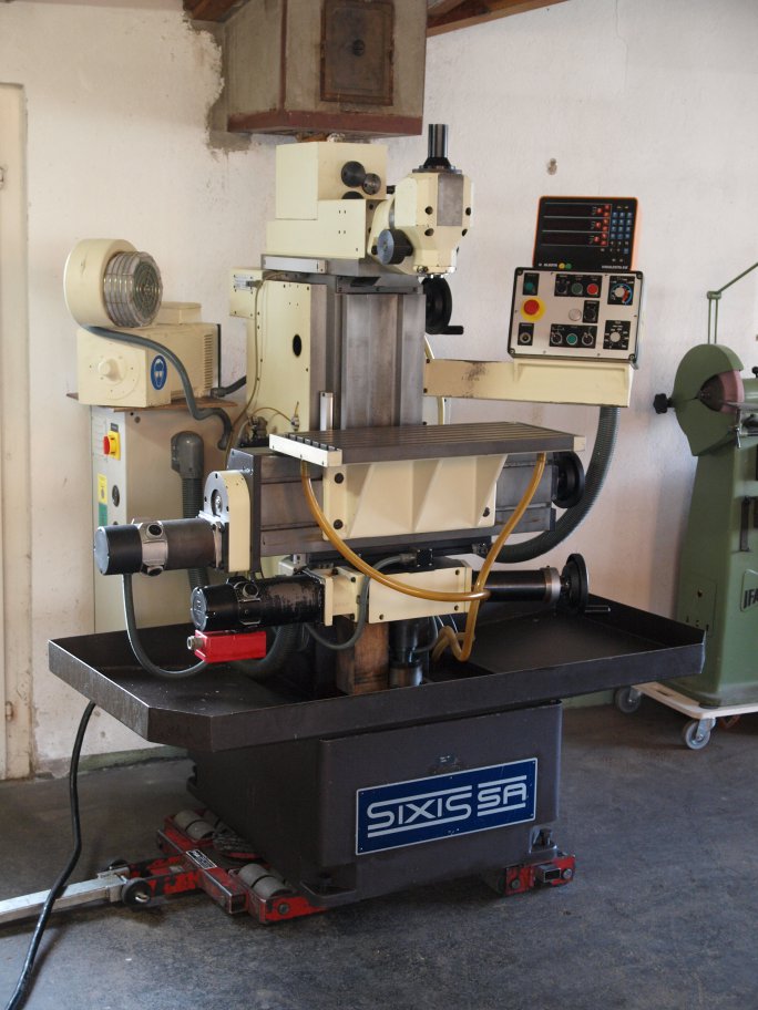
Neat machine btw...
John
Please Log in or Create an account to join the conversation.
- andypugh
-

- Offline
- Moderator
-
- Posts: 19833
- Thank you received: 4625
In the end I want to close the servo loops with the glass scales on each axis of my mill.
I think that is the only way.
The existing Tachos on the motors connect to the servo drives, and will continue to do so. That allows the drives to work in a closed-loop velocity mode.
ie, 10V from LinuxCNC = 100% servo speed, 1V from LinuxCNC = 10% speed, 9v battery and no controller at all = 90% speed.
Then, inside LinuxCNC you run a position control loop which considers the feedback from the glass scales, and sends out a velocity command to the drives according to how far out of position the carriage is.
I hope that your glass scales have quadrature output though, or it gets a little tricksy.
Please Log in or Create an account to join the conversation.