drive wiring
- accuartisans
- Offline
- New Member
-

- Posts: 10
- Thank you received: 0
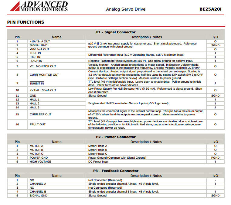
drive pin 9 = /INH --> relay NC contact
drive pin 2 =GND--> relay COM contact
Also, in the hal config when we have:
# create a signal for the estop loopback
net estop-loop iocontrol.0.user-enable-out => iocontrol.0.emc-enable-in
iocontrol.0.user-enable-out refers to TB8 - pin 17 (Output 0) ??
So I'm guessing here but iocontrol.0.emc-enable-in TB8 - pin 1 (Input 0) is where we wire up the E-Stop circuit to signal that we have unlocked the E-Stop button? I am unsure what the diagram would look like, does E-Stop go to Ground/COM when it's closed or is a closed loop switch? If it's closed one end of the E-Stop goes to Input 0 and the other end goes where? I realize these are elementary questions, but I am learning and I believe this is the glue that puts it together.
My setup is the 7I80DB+7I77 running debian jessie (3.14.12 rt preempt kernel) on a Gigabyte J1800N-D2H motherboard.
Also, the relay that I planned on using are the Omron LY2-DC24 as I have several of them with the base.
Thanks for the help
Please Log in or Create an account to join the conversation.
- BigJohnT
-

- Offline
- Administrator
-

- Posts: 7000
- Thank you received: 1176
accuartisans wrote:
# create a signal for the estop loopback
net estop-loop iocontrol.0.user-enable-out => iocontrol.0.emc-enable-in
iocontrol.0.user-enable-out refers to TB8 - pin 17 (Output 0) ??
Not unless you make it so. By default those HAL pins don't leave the software layer.
One way of wiring things is:
iocontrol.0.user-enable-out -> GPIO output pin -> main contactor relay -> ESOP11 -> ESTPO2 -> ESTOPN -> GPIO input pin -> iocontrol.0.emc-enable-in
(I practice the GPIO output pin probably doesn't have enough current capacity to drive the main contactor but can drive a solid-state relay quite well)
So I'm guessing here but iocontrol.0.emc-enable-in TB8 - pin 1 (Input 0) is where we wire up the E-Stop circuit to signal that we have unlocked the E-Stop button?
No GPIO pins are connected to anything unless specifically connected in the HAL file. You would need lines like
net estop-out iocontrol.0.user-enable-out => hm2_7i80.0.7i77.0.0.output-000
net estop-in hm2_7i80.0.7i77.0.0.input-000 => iocontrol.0.emc-enable-in
Please Log in or Create an account to join the conversation.