Facets on corners using G2 arcs?
- DaBit
- Offline
- Platinum Member
-

Less
More
- Posts: 446
- Thank you received: 35
05 Jan 2015 06:19 - 05 Jan 2015 06:19 #54560
by DaBit
Facets on corners using G2 arcs? was created by DaBit
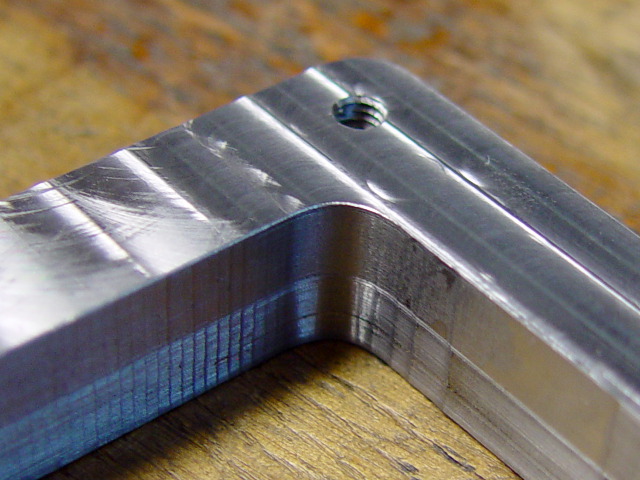
Has anyone seen this before?
My mill tends to mill facets on arcs, but only does so during G2 arcs.
Climb milling. Inside corners are fine:
Outside corners, not so:
The above two pictures were already from a slower run (850mm/min, 6500rpm on a 6mm carbide endmill) where following errors stayed below 0,02mm.
The initial run was much faster: 11000rpm, 1900mm/min. Facets are the same, so I doubt it is servo-related. I also plotted the axis0/1 ferror during the milling itself, and did not see a following error larger than 0,02mm.
LinuxCNC 2.8.0~pre, new TP enabled, G64 tolerance set to 0.02.
G-code for this part was generated with Autodesk Fusion360/Cam360, but I have seen this happening before in softer materials also with CamBam generated code. Initially I blamed it on the CAM, but I am not so sure now.
Link to the ngc file: dl.dropboxusercontent.com/u/2762301/6mm_frezen.ngc
As you can see: all arcs.
If nobody comes up with 'hey, I had that too, your problem is xyzabc' I will try to isolate it.
Last edit: 05 Jan 2015 06:19 by DaBit.
Please Log in or Create an account to join the conversation.
- Todd Zuercher
-

- Offline
- Platinum Member
-

Less
More
- Posts: 5020
- Thank you received: 1464
05 Jan 2015 09:06 #54564
by Todd Zuercher
Replied by Todd Zuercher on topic Facets on corners using G2 arcs?
I have seen very similar results on a machine with servo tuning issues (a Fanuc control though) I'd also look carefully at backlash issues.
Please Log in or Create an account to join the conversation.
- BigJohnT
-

- Offline
- Administrator
-

Less
More
- Posts: 7000
- Thank you received: 1176
05 Jan 2015 20:46 #54571
by BigJohnT
Replied by BigJohnT on topic Facets on corners using G2 arcs?
It looks too uniform to be a mechanical issue, I suspect your CAM program is converting arcs to lines on the outside corner.
JT
JT
Please Log in or Create an account to join the conversation.
- Todd Zuercher
-

- Offline
- Platinum Member
-

Less
More
- Posts: 5020
- Thank you received: 1464
05 Jan 2015 22:43 #54579
by Todd Zuercher
Replied by Todd Zuercher on topic Facets on corners using G2 arcs?
Do the facets show on the back plot screen? If it were something goofy that the new tool planner is doing I think it would show up there.
Please Log in or Create an account to join the conversation.
- DaBit
- Offline
- Platinum Member
-

Less
More
- Posts: 446
- Thank you received: 35
05 Jan 2015 22:57 #54581
by DaBit
Replied by DaBit on topic Facets on corners using G2 arcs?
I am pretty sure it is not backlash. I am using double preloaded ballnuts on the screws and the screws are also supported with four angular contact bearings on each screw (two on each side, fixed-fixed setup). Checked tightness of the preloading screws, and theye were not loose. Besides: if it was backlash, I would see it as steps in the following error since the linear scale measurement is used as axis.N.motor-pos-fb.
Same with the servo loops: if the servo system goes crazy I would expect to see a ferror.
A remote possibility is that one of the scales is not measuring correctly and suffering from some 'stiction' or so. Although when that would be the case I would expect a more velocity-dependant result. Easy enough to take the scales out of the equation though (halcmd setp xscale_pid.max-output 0.0', done), so worth a try.
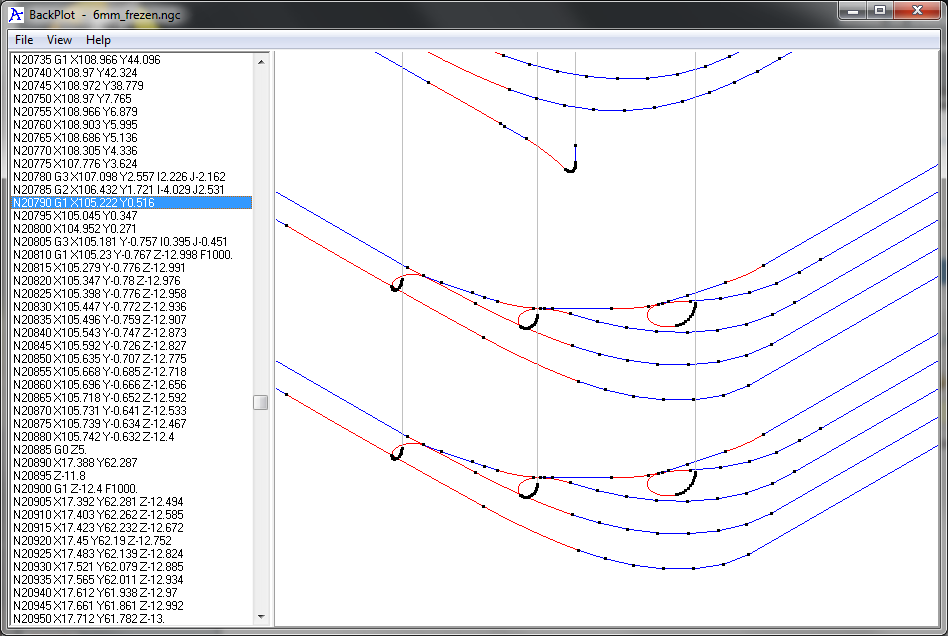
It seems to be a CAM-problem after all:
What exactly causes the problem is almost impossible to see in the backplot with those adaptive toolpaths. Backplot looks like a plate filled with spaghetti. I might want to open the file in an AXIS config so I can click on a G-code line and have it highlighted in the preview. Gmoccapy cannot do that yet.
Please Log in or Create an account to join the conversation.
- Todd Zuercher
-

- Offline
- Platinum Member
-

Less
More
- Posts: 5020
- Thank you received: 1464
05 Jan 2015 23:27 - 05 Jan 2015 23:34 #54583
by Todd Zuercher
Replied by Todd Zuercher on topic Facets on corners using G2 arcs?
Last edit: 05 Jan 2015 23:34 by Todd Zuercher.
Please Log in or Create an account to join the conversation.
- DaBit
- Offline
- Platinum Member
-

Less
More
- Posts: 446
- Thank you received: 35
05 Jan 2015 23:54 #54587
by DaBit
Replied by DaBit on topic Facets on corners using G2 arcs?
I am trying to switch to Autodesk Fusion360 / Cam360 as my 3D CAD/CAM-system since as a noncommercial user I am allowed to use it for free and so far I seem to be able to do with it what I need. That beats, uhm, perpetual evaluation licenses of Solidworks and limited-feature software like DesignSpark Mechanical and FreeCAD for example
But I guess there is a learning curve involved; I should have used a contour finish milling pass for example but I was stupid enough to think the software did that for me. That Cam360 is in the middle between 'Tell me exactly what you want do do'-CamBam and 'Let me solve that for you'-SolidCAM. And probably there is a reason why it is still free for noncommerical use and quite inexpensive for commercial use...
But I guess there is a learning curve involved; I should have used a contour finish milling pass for example but I was stupid enough to think the software did that for me. That Cam360 is in the middle between 'Tell me exactly what you want do do'-CamBam and 'Let me solve that for you'-SolidCAM. And probably there is a reason why it is still free for noncommerical use and quite inexpensive for commercial use...
Please Log in or Create an account to join the conversation.
Time to create page: 0.148 seconds


