Modbus Help - MB2HAL
- racedirector
- Offline
- Elite Member
-

- Posts: 231
- Thank you received: 42
Inserted classicladder into my config and selected the modbud stuff in the hope of getting my Hitachi X200 VFD up and running. However I don't quite understand how it relates to reading/writing to the VFD.
My VFD goes active due to the display showing 0.00 and waiting for some input. However, the modbus classicladder panel shows failure and the commandline window just spews modbus errors.
In Mach3 the following settings work in the modbus setup window:
cfg#0 Start/Run | Port:1 | Slave:1 | Refresh:50 ms | Modbus Var: 0 | Register: 2 | Direction: Output Coils
cfg#1 Frequency | Port: 1 | Slave: 1 | Refresh: 75 ms | Modbus Var: 1 | Register: 1 : Direction: Output Holding
And what I can't figure out is where this info lies in the classicladder config.
Can anyone help clear the fog from around my brain?
Cheers
Please Log in or Create an account to join the conversation.
- VNR
- Offline
- Junior Member
-

- Posts: 24
- Thank you received: 5
My VFD goes active due to the display showing 0.00 and waiting for some input. However, the modbus classicladder panel shows failure and the commandline window just spews modbus errors.
Probably is a configuration error:
Paste the errors to see what it is reporting.
It should help to have the Hitachi X200 VFD PDF manual to see what is the correct configuration and registers information, or may be you can extract it from the mach3 configuration screen.
Also check:
- Port number and port speed.
- If the driver is configured to 8-N-1 (bits, parity, stop bits).
- If the driver support RTU modbus (not ascii).
- Modbus address (device address)
- Registers address (decimal?/hexadecimal?) and configuration.
Here you know: port is 1, slave is 1, Output Coils probably is Write_Coils,cfg#0 Start/Run | Port:1 | Slave:1 | Refresh:50 ms | Modbus Var: 0 | Register: 2 | Direction: Output Coils
cfg#1 Frequency | Port: 1 | Slave: 1 | Refresh: 75 ms | Modbus Var: 1 | Register: 1 : Direction: Output Holding
Output Holding probably is Write_Regs, Register 2 probably is the address of the register.
Regards,
Victor
Please Log in or Create an account to join the conversation.
- racedirector
- Offline
- Elite Member
-

- Posts: 231
- Thank you received: 42
Thanks for stopping by, appreciate it.
I'll get all that when I get home from work tonight, you're right it is a config error on my part.
Cheers
Bruce
Please Log in or Create an account to join the conversation.
- racedirector
- Offline
- Elite Member
-

- Posts: 231
- Thank you received: 42
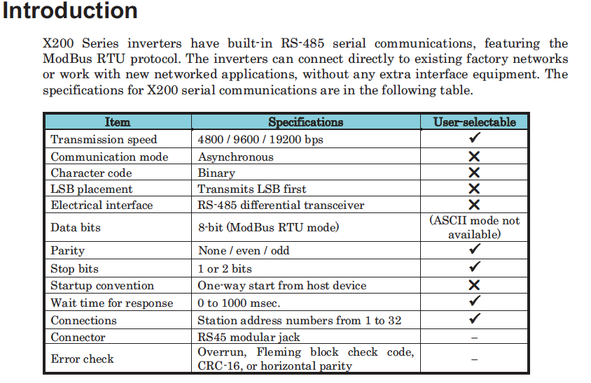
Firstly, the full X200 manual is here: www.dietzelectric.com/documents/Hitachi%20X200%20Manual.pdf
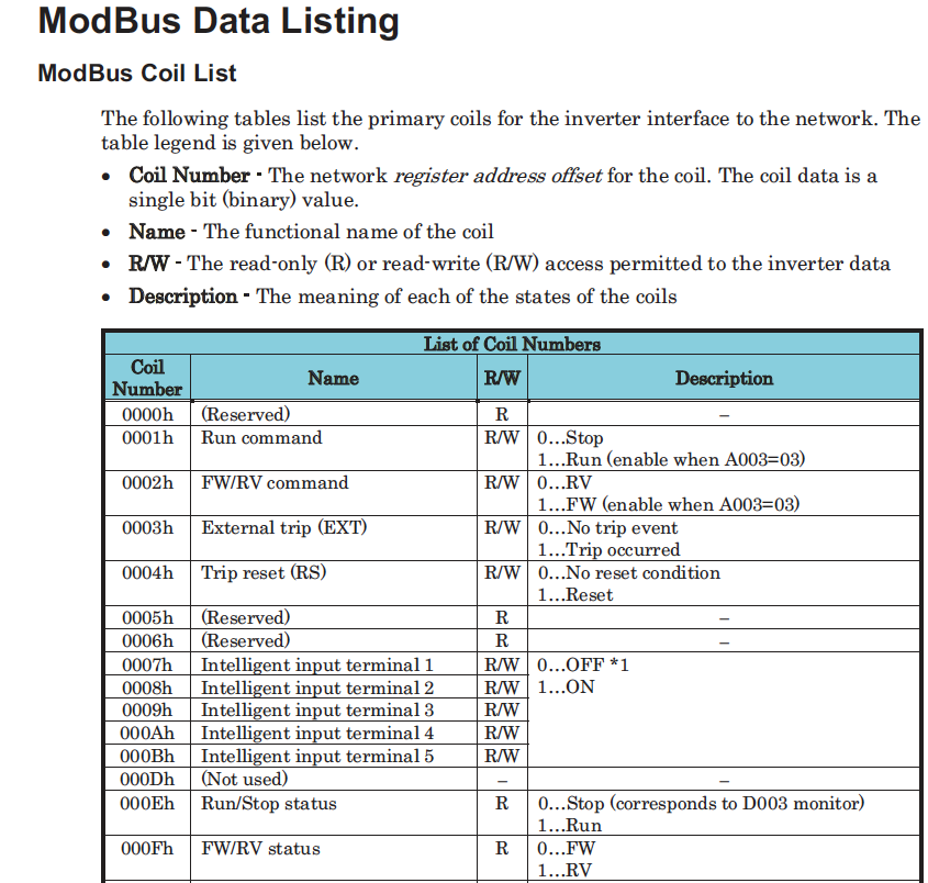
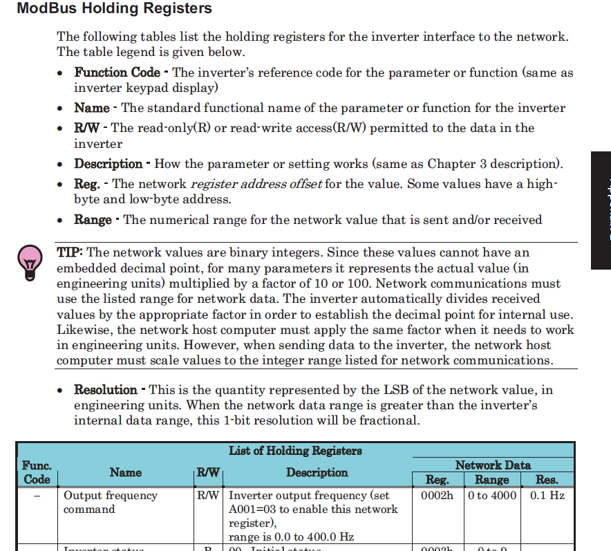
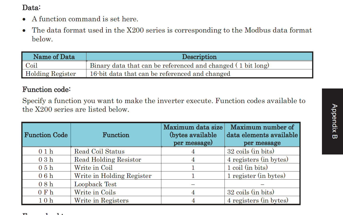
Attached are screen grabs of the relevant sections, Coils, Register and Functions
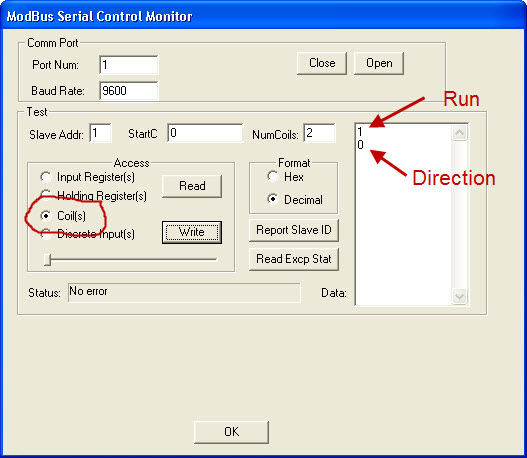
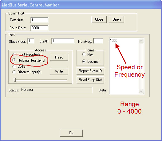
My VFD is set to talk @ 9600 N-8-1 on ttys0. I found out that the Mach3 Modbus Output Coils *IS* Write Coils. X200 has 2 coils of interest starting at 0 writing 2. These set the stat=us to either Run or Stop. Output Registers *IS* Write Register. The X200 has one register of interest starting at 1 writing 1. This sets the frequency.
I tried ClassicLadder and finally got it not spewing errors. I switched to Mb2Hal with the following ini and additions to my hal file.
So far I haven't got the VFD to do anything, I need to figure out how to join everything up so I can M3 etc to control it. I must admit I am further long than the other day.... I think.
If the contents of the ini can be confirmed I can do a little more research on connecting things to hsl pins etc
Cheers
Bruce
Please Log in or Create an account to join the conversation.
- racedirector
- Offline
- Elite Member
-

- Posts: 231
- Thank you received: 42
Please Log in or Create an account to join the conversation.
- racedirector
- Offline
- Elite Member
-

- Posts: 231
- Thank you received: 42
Screenshot from the MB2hal session
Please Log in or Create an account to join the conversation.
- VNR
- Offline
- Junior Member
-

- Posts: 24
- Thank you received: 5
change in the modbus ini file:
SLOWDOWN=0.0 -> SLOWDOWN=3.0
DEBUG=1 -> DEBUG=3 (both of them)
you should get a better level of debug messages
paste the result here, please use a bigger screenshot than before, i am getting old
Cheers
Victor
Please Log in or Create an account to join the conversation.
- racedirector
- Offline
- Elite Member
-

- Posts: 231
- Thank you received: 42
Hope these ones are better
Cheers
Bruce
Please Log in or Create an account to join the conversation.
- racedirector
- Offline
- Elite Member
-

- Posts: 231
- Thank you received: 42
So now mb2hal.remoteIOcfg.0 is now mb2hal.spindlerun.0 and mb2hal.remoteIIOcfg.1 is now mb2hal.spindlerun.1 and mb2hal.remoteIOin.00 is now mb2hal.spindlefreq.00
So I suppose my next task is to figure out how to connect those to usable hal pins
EDIT: I think mb2hal.spindlerun.0 controls the run/stop signal and mb2hal.spindlerun.1 controls forward/reverse so both should be renamed to something like spindle-run-dir given the info (from a MACH3 post) in these pics:
Cheers
Bruce
Please Log in or Create an account to join the conversation.
- VNR
- Offline
- Junior Member
-

- Posts: 24
- Thank you received: 5
It is working.Okie dokie, here's revised screen grabs - DEBUG on each txn set to 3, SLOWDOWN set to 3 plus I managed to get halrun to show me the pins in mb2hal.
Dont' forget to reduce the SLOWDOWN and DEBUG parameter once on production.
That's right, but first use halcmd command line to test, then configure the INI file.So I suppose my next task is to figure out how to connect those to usable hal pins
EDIT: I think mb2hal.spindlerun.0 controls the run/stop signal and mb2hal.spindlerun.1 controls forward/reverse so both should be renamed to something like spindle-run-dir given the info (from a MACH3 post) in these pics
Cheers,
Victor
Please Log in or Create an account to join the conversation.

