Squaring machine / spindle
- danimal300
- Offline
- Senior Member
-

Less
More
- Posts: 54
- Thank you received: 1
30 Jun 2016 02:59 #76817
by danimal300
Squaring machine / spindle was created by danimal300
I have been making some pretty good parts, and dimensionally I am seeing roughly .001 accuracy most of the time. The problem comes when I do multiple setups. I have shifts no matter how meticulously I re-align the datum for the setup. I guess I am just looking for some suggestions on how to track down and correct errors for the home CNC guy with a limited budget.
Backlash: I have measured and set backlash values in the .ini file, though I have some concern with this. The method I used, I set my dial caliper and jogged the machine in .1 increments. I adjusted the backlash value until the axis movement stopped at exactly the same point on the dial for any incremental movement. I could also move to 0 almost exactly from any position just by entering in the measured value. But when I turn the jog speed way way down, and alternate the direction of travel, I see a shift of .005 ish on all axis. I am just trying to test the takeup, but it does change position of the axis. When machining I can see the positions of this change (apex of curves have a little bump) Other than the bump, the accuracy is about .001"
When I change setups, there is often a slight rotation of the part leading to a shift that gets worse the further you get from the x,y zeroing point. I Figured this has to be something to do with my vice, but after milling the part, I measured the indexing fixed jaw and saw about .00025 difference across the 4" span. My dial indicator is .0005 accuracy or so it claims.
Any recommendations would be greatly appreciated
Please Log in or Create an account to join the conversation.
- danimal300
- Offline
- Senior Member
-
Less
More
- Posts: 54
- Thank you received: 1
30 Jun 2016 03:09 - 30 Jun 2016 03:24 #76818
by danimal300
Replied by danimal300 on topic Squaring machine / spindle
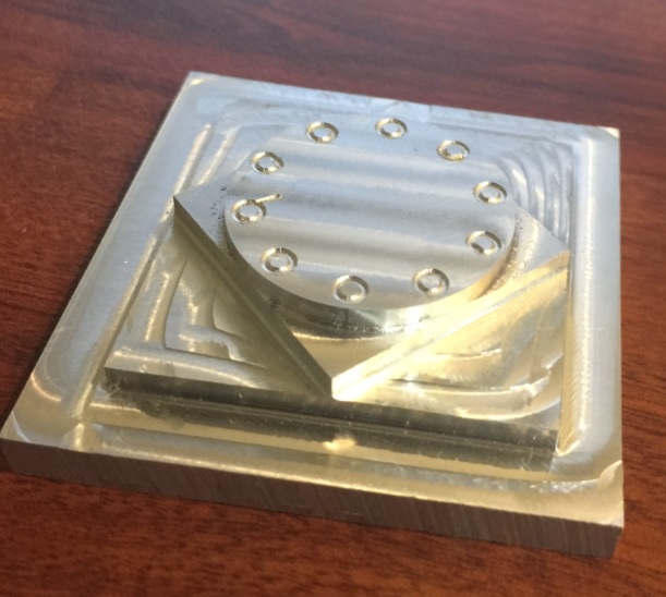
Here is my circle diamond square test.
You can see the little bump at the apex of the circle that I was talking about.
There is some tool deflection because I was trying some adaptive HSM tool paths and incrementally walking up the feed speed for each corner to see how they performed. This was cut with a long fluted 5/16 end mill with 1.6" of stick-out, depth of cut was .2 or .3" with a .2 max stopover so I knew that there would be some deflection.
.
Last edit: 30 Jun 2016 03:24 by danimal300.
Please Log in or Create an account to join the conversation.
- danimal300
- Offline
- Senior Member
-
Less
More
- Posts: 54
- Thank you received: 1
30 Jun 2016 03:20 #76819
by danimal300
Replied by danimal300 on topic Squaring machine / spindle
Here is the most recent part that I made, and you can see that there is a rotational offset between the two setups.
Please Log in or Create an account to join the conversation.
- BigJohnT
-

- Offline
- Administrator
-

Less
More
- Posts: 3990
- Thank you received: 994
30 Jun 2016 10:24 #76827
by BigJohnT
If you have backlash then you will not get accurate parts. Setting backlash in the ini is only a poor fix for a hardware problem.
Can you elaborate on what a "setup" is? Even with poor lead screws and backlash the same part made in the same place should come out reasonably the same. It does sound as if your expecting more than your machine can deliver and pushing the envelope with your tooling.
JT
Replied by BigJohnT on topic Squaring machine / spindle
I have been making some pretty good parts, and dimensionally I am seeing roughly .001 accuracy most of the time. The problem comes when I do multiple setups. I have shifts no matter how meticulously I re-align the datum for the setup. I guess I am just looking for some suggestions on how to track down and correct errors for the home CNC guy with a limited budget.
Backlash: I have measured and set backlash values in the .ini file, though I have some concern with this. The method I used, I set my dial caliper and jogged the machine in .1 increments. I adjusted the backlash value until the axis movement stopped at exactly the same point on the dial for any incremental movement. I could also move to 0 almost exactly from any position just by entering in the measured value. But when I turn the jog speed way way down, and alternate the direction of travel, I see a shift of .005 ish on all axis. I am just trying to test the takeup, but it does change position of the axis. When machining I can see the positions of this change (apex of curves have a little bump) Other than the bump, the accuracy is about .001"
When I change setups, there is often a slight rotation of the part leading to a shift that gets worse the further you get from the x,y zeroing point. I Figured this has to be something to do with my vice, but after milling the part, I measured the indexing fixed jaw and saw about .00025 difference across the 4" span. My dial indicator is .0005 accuracy or so it claims.
Any recommendations would be greatly appreciated
If you have backlash then you will not get accurate parts. Setting backlash in the ini is only a poor fix for a hardware problem.
Can you elaborate on what a "setup" is? Even with poor lead screws and backlash the same part made in the same place should come out reasonably the same. It does sound as if your expecting more than your machine can deliver and pushing the envelope with your tooling.
JT
The following user(s) said Thank You: danimal300
Please Log in or Create an account to join the conversation.
- danimal300
- Offline
- Senior Member
-
Less
More
- Posts: 54
- Thank you received: 1
30 Jun 2016 14:05 - 30 Jun 2016 14:27 #76841
by danimal300
I have some decent quality Thompson ball-screws and pre-loaded ball nuts, but the system still has around .003 backlash on the x and y axis, and .007 on the z axis. I have adjusted the gib's pretty tight (well just barely feeling drag) and oiled everything prior to running the circle square test. The engraving for the part pictured was done with a 1/32 ball end mill, and it came out pretty good. I can barely find a start stop point on the pattern, so I know that the backlash compensation is working well enough for that application.
By setup I mean machining one side, removing the part and machining the another. When the positions are changed, I have to change the axis configuration in CAM and when the datum's and origin are selected so that the axis and touch off points are correct it called a "setup" in the CAM software. All tool paths for that face go into that setup folder, so I just figured that was the common nomenclature.
I may be expecting more than it can deliver, I am just looking for suggestions or helpful tools and methods for measuring machine geometry and positional accuracy. I found one over at cnczone with 123 blocks that I am going to try. I was pushing the tooling quite a bit for the test, and it was because they are new end mills that I am trying out. They are the 45 degree aluminum specific end-mills, and I wanted to see it the cut angle made a difference, and it did, but not as much as I would have hoped.
Replied by danimal300 on topic Squaring machine / spindle
If you have backlash then you will not get accurate parts. Setting backlash in the ini is only a poor fix for a hardware problem.
Can you elaborate on what a "setup" is? Even with poor lead screws and backlash the same part made in the same place should come out reasonably the same. It does sound as if your expecting more than your machine can deliver and pushing the envelope with your tooling.
JT
I have some decent quality Thompson ball-screws and pre-loaded ball nuts, but the system still has around .003 backlash on the x and y axis, and .007 on the z axis. I have adjusted the gib's pretty tight (well just barely feeling drag) and oiled everything prior to running the circle square test. The engraving for the part pictured was done with a 1/32 ball end mill, and it came out pretty good. I can barely find a start stop point on the pattern, so I know that the backlash compensation is working well enough for that application.
By setup I mean machining one side, removing the part and machining the another. When the positions are changed, I have to change the axis configuration in CAM and when the datum's and origin are selected so that the axis and touch off points are correct it called a "setup" in the CAM software. All tool paths for that face go into that setup folder, so I just figured that was the common nomenclature.
I may be expecting more than it can deliver, I am just looking for suggestions or helpful tools and methods for measuring machine geometry and positional accuracy. I found one over at cnczone with 123 blocks that I am going to try. I was pushing the tooling quite a bit for the test, and it was because they are new end mills that I am trying out. They are the 45 degree aluminum specific end-mills, and I wanted to see it the cut angle made a difference, and it did, but not as much as I would have hoped.
Last edit: 30 Jun 2016 14:27 by danimal300.
Please Log in or Create an account to join the conversation.
- danimal300
- Offline
- Senior Member
-
Less
More
- Posts: 54
- Thank you received: 1
30 Jun 2016 14:21 #76842
by danimal300
Replied by danimal300 on topic Squaring machine / spindle
I guess what I am looking for is a way to determine if the offset is due to the machine x, y axis not being perpendicular, or if something else is causing the problem (maybe the y axis stepper is moving a tiny increment further per step than the x axis motor) or something along those lines where a simple machine calibration might make all the difference.
The confusing part is that when I measure moving only one axis at a time, I can see very little error. almost nothing. Sometimes I have to take a zoomed in picture with my phone, change the position, and compare the two images side by side to see any difference at all. But then I machine a part, and there are .005 worth of offset at the end of a 2.5" part, and divots where the x and y axis changed direction in a curve.
The confusing part is that when I measure moving only one axis at a time, I can see very little error. almost nothing. Sometimes I have to take a zoomed in picture with my phone, change the position, and compare the two images side by side to see any difference at all. But then I machine a part, and there are .005 worth of offset at the end of a 2.5" part, and divots where the x and y axis changed direction in a curve.
Please Log in or Create an account to join the conversation.
- Todd Zuercher
-

- Away
- Platinum Member
-

Less
More
- Posts: 4761
- Thank you received: 1463
30 Jun 2016 14:42 #76846
by Todd Zuercher
Replied by Todd Zuercher on topic Squaring machine / spindle
If you get different results moving both axis at the same time, than when you move one then the other, sounds like you are loosing steps. Look at things like a week power supply, marginal step signals, or cross-talk in the signal cabling.
The following user(s) said Thank You: danimal300
Please Log in or Create an account to join the conversation.
- danimal300
- Offline
- Senior Member
-
Less
More
- Posts: 54
- Thank you received: 1
30 Jun 2016 15:32 - 30 Jun 2016 15:34 #76849
by danimal300
Replied by danimal300 on topic Squaring machine / spindle
I have grounded all the cable shields for the stepper motor conductors to the common ground, and do not see a lot of cross talk when I hook an o-scope to the non running motor.
I will look again at my base period and see if I need to up the value a little bit. I did tweak it down until I stopped getting errors, but it is possible that it might be just a hair too low. I have made 3 of these identical parts, and they all turn out the exact same way. At first I thought that I did not set the origin correctly. Then after the second one I rechecked the vice and verified that it was aligned. The third one I checked and re-checked everything and spend 15 minutes perfectly positioning the origin. Exactly the same results.
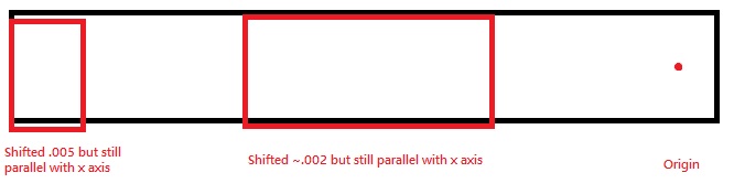
In the part above, the roughing tool path was an adaptive clearing HSM tool path, then it was followed with a contour at final dimension. The origin was set to the hole drilled all the way through the part. The mismatch for the rectangular section is ~.002 all the way across, shifted only in the y axis. The angled part on the tip of the part was shifted about .005 only along the y axis, but again the face of the shifted part is parallel to the x axis. See picture below, kinda hard to explain.
I will look again at my base period and see if I need to up the value a little bit. I did tweak it down until I stopped getting errors, but it is possible that it might be just a hair too low. I have made 3 of these identical parts, and they all turn out the exact same way. At first I thought that I did not set the origin correctly. Then after the second one I rechecked the vice and verified that it was aligned. The third one I checked and re-checked everything and spend 15 minutes perfectly positioning the origin. Exactly the same results.
In the part above, the roughing tool path was an adaptive clearing HSM tool path, then it was followed with a contour at final dimension. The origin was set to the hole drilled all the way through the part. The mismatch for the rectangular section is ~.002 all the way across, shifted only in the y axis. The angled part on the tip of the part was shifted about .005 only along the y axis, but again the face of the shifted part is parallel to the x axis. See picture below, kinda hard to explain.
Last edit: 30 Jun 2016 15:34 by danimal300.
Please Log in or Create an account to join the conversation.
- danimal300
- Offline
- Senior Member
-
Less
More
- Posts: 54
- Thank you received: 1
30 Jun 2016 15:33 #76850
by danimal300
Replied by danimal300 on topic Squaring machine / spindle
Please Log in or Create an account to join the conversation.
- Todd Zuercher
-
- Away
- Platinum Member
-
Less
More
- Posts: 4761
- Thank you received: 1463
30 Jun 2016 17:25 - 30 Jun 2016 17:28 #76860
by Todd Zuercher
Replied by Todd Zuercher on topic Squaring machine / spindle
If the axis or the vise were out of square the sides would not be parallel, but skewed the same as the pieces are out of place.
It really does seem more like a missing step problem. After running the part did (could) you recheck your origin point to make sure it had not shifted?
Changing the base thread speed likely won't effect it unless overruns are significant and/or step timing is marginal. I'd look more closely at things like increasing the step space timing, reducing max acceleration and velocity. Set the step timings for the longest times you need to reach your max feed rate, rather than the drives spec limits.
Last edit: 30 Jun 2016 17:28 by Todd Zuercher.
The following user(s) said Thank You: danimal300
Please Log in or Create an account to join the conversation.
Time to create page: 0.272 seconds