Help with M542T driver to Breakout board connections
- weyepx
- Offline
- New Member
-

Less
More
- Posts: 5
- Thank you received: 0
23 Mar 2017 02:49 #90099
by weyepx
Help with M542T driver to Breakout board connections was created by weyepx
I am new to this and building my first CNC machine from scratch.
I am a little confused on wiring the drivers to the breakout board I have. It is a 4 Axis USB CNC Card Controller Interface Board for Mach3 DIY. So it says.
The BOB has the following points;
DIR
Z: 5V/GRND
PUL
DIR
X: 5V/GRND
PUL
DIR
Y: 5V/GRND
PUL
A: Assume not using since I only have 3 Axis unit (3 motors)
There is another location on the board for Z-Tool Off-Set, 7-points are Grnd, Y+, Z-, Z+, Y-, X-, X+.
The M542T has the following points;
PUL+ (+5V)
PUL- (PUL)
DIR+ (+5V)
DIR- (DIR)
ENA+ (+5V)
ENA- (ENA)
What goes to what?
I also have NEMA 23 Stepper motors (23HS45-3504S)
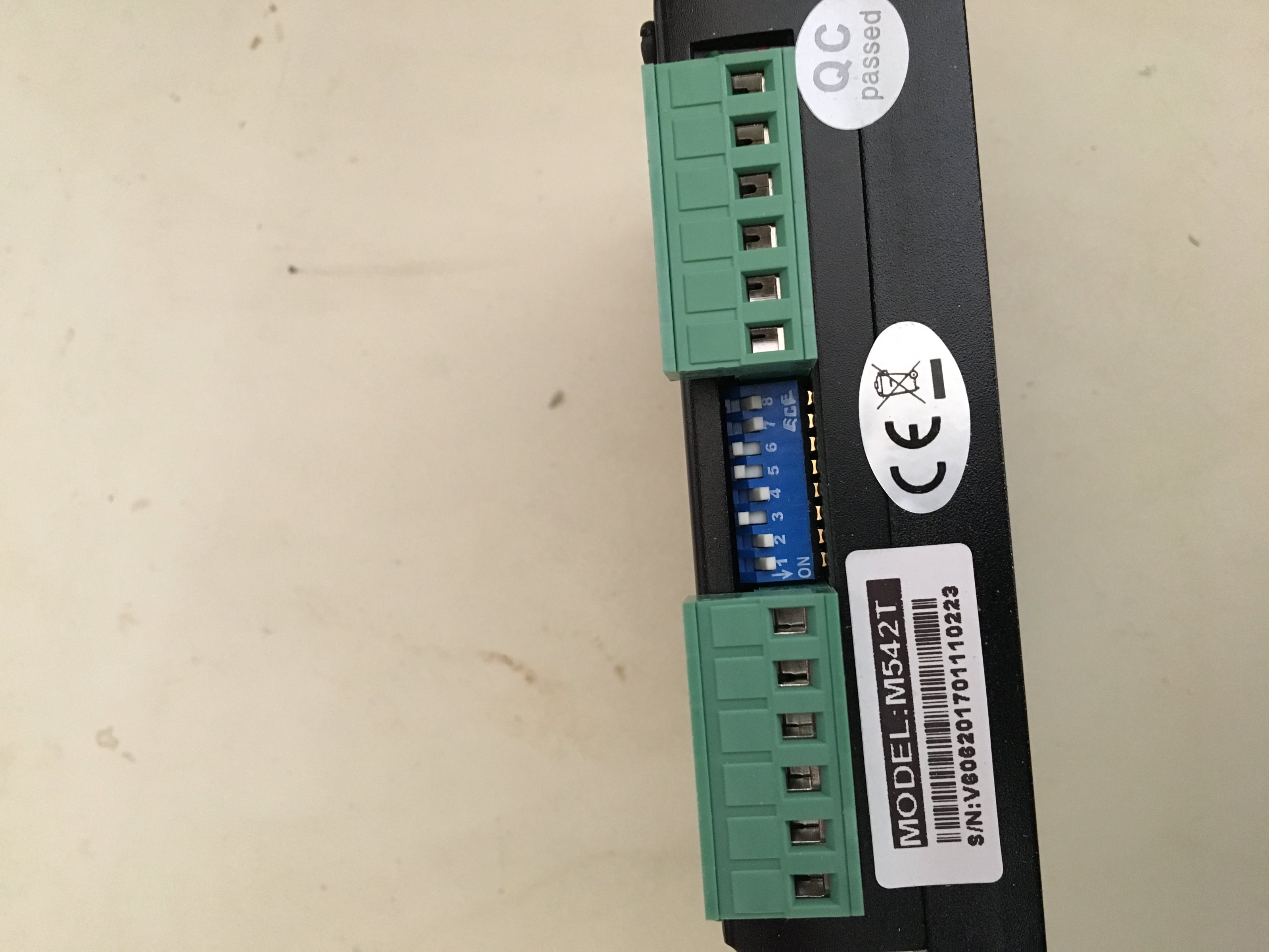
I have the pin settings on the drivers as follows:
1-On
2-On
3-Off
4-On
5-Off
6-Off
7-On
8-On
Any and all help is greatly appreciated.
Thanks,
Paul
I am a little confused on wiring the drivers to the breakout board I have. It is a 4 Axis USB CNC Card Controller Interface Board for Mach3 DIY. So it says.
The BOB has the following points;
DIR
Z: 5V/GRND
PUL
DIR
X: 5V/GRND
PUL
DIR
Y: 5V/GRND
PUL
A: Assume not using since I only have 3 Axis unit (3 motors)
There is another location on the board for Z-Tool Off-Set, 7-points are Grnd, Y+, Z-, Z+, Y-, X-, X+.
The M542T has the following points;
PUL+ (+5V)
PUL- (PUL)
DIR+ (+5V)
DIR- (DIR)
ENA+ (+5V)
ENA- (ENA)
What goes to what?
I also have NEMA 23 Stepper motors (23HS45-3504S)
I have the pin settings on the drivers as follows:
1-On
2-On
3-Off
4-On
5-Off
6-Off
7-On
8-On
Any and all help is greatly appreciated.
Thanks,
Paul
Please Log in or Create an account to join the conversation.
- tommylight
-

- Away
- Moderator
-

Less
More
- Posts: 21743
- Thank you received: 7430
23 Mar 2017 10:12 #90109
by tommylight
Replied by tommylight on topic Help with M542T driver to Breakout board connections
First, be sure it is a USB BOB, does it have a parallel port on it? Most of them have parallel port for comunication and a USB port for powering the board only. Also you should check for the +5V/grnd as you need that to be set to +5V OR GND and based on that vire the drive. Basicly, you need to wire all 3 + or gnd inputs to that output, and the other ones to their respective outputs.
As for the drives, take a picture and post it here showing the switches and the writing. I have 2 types from the same manufacturer and they do not have the same switch settings.
As for the drives, take a picture and post it here showing the switches and the writing. I have 2 types from the same manufacturer and they do not have the same switch settings.
Please Log in or Create an account to join the conversation.
- weyepx
- Offline
- New Member
-
Less
More
- Posts: 5
- Thank you received: 0
23 Mar 2017 21:48 #90163
by weyepx
Replied by weyepx on topic Help with M542T driver to Breakout board connections
The BOB says its for a 4 Axis USB CNC Card Controller Interface Board for Mach3.
If anyone can tell if the USB is for power or not, that would be helpful. I don't think it is because you can see power supply on the top left corner of the front of the board, On the back it is showing on the top right side. You can also see all the marking points for termination as I had described earlier. Also attached is the driver and the pin settings I have selected based on best guess from information supplied by the drawing for the stepper motors 35HS45-3504S.
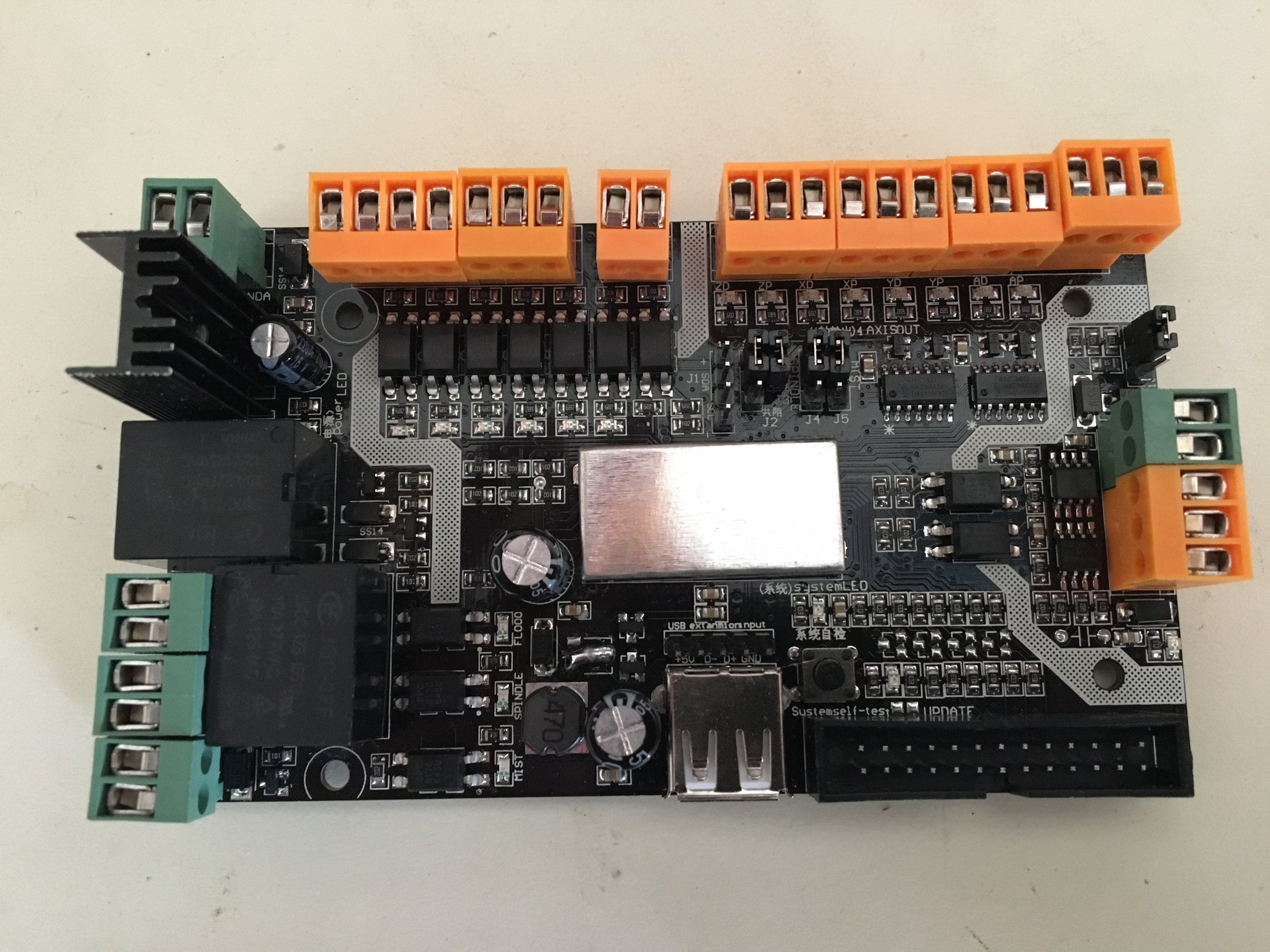
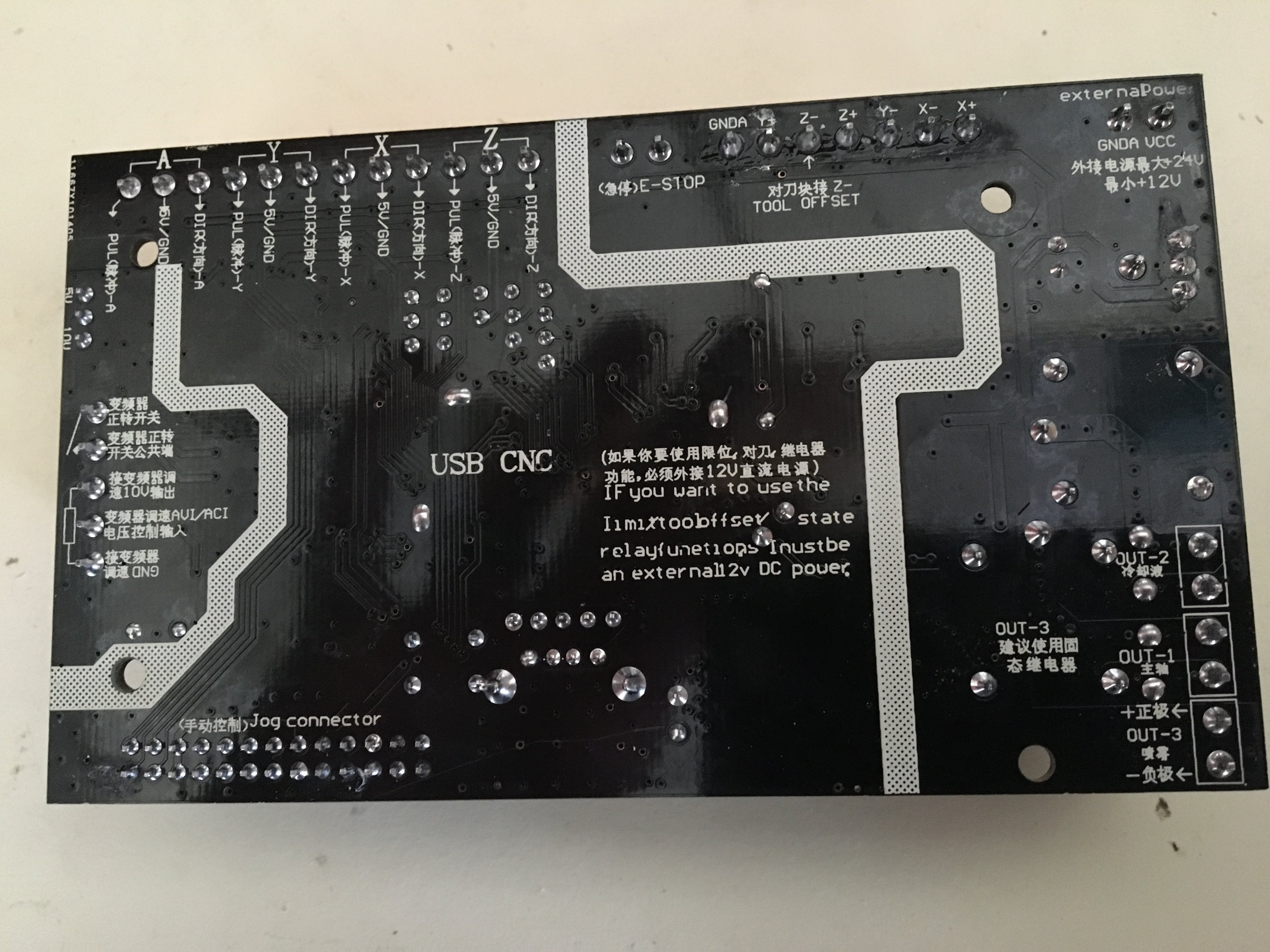
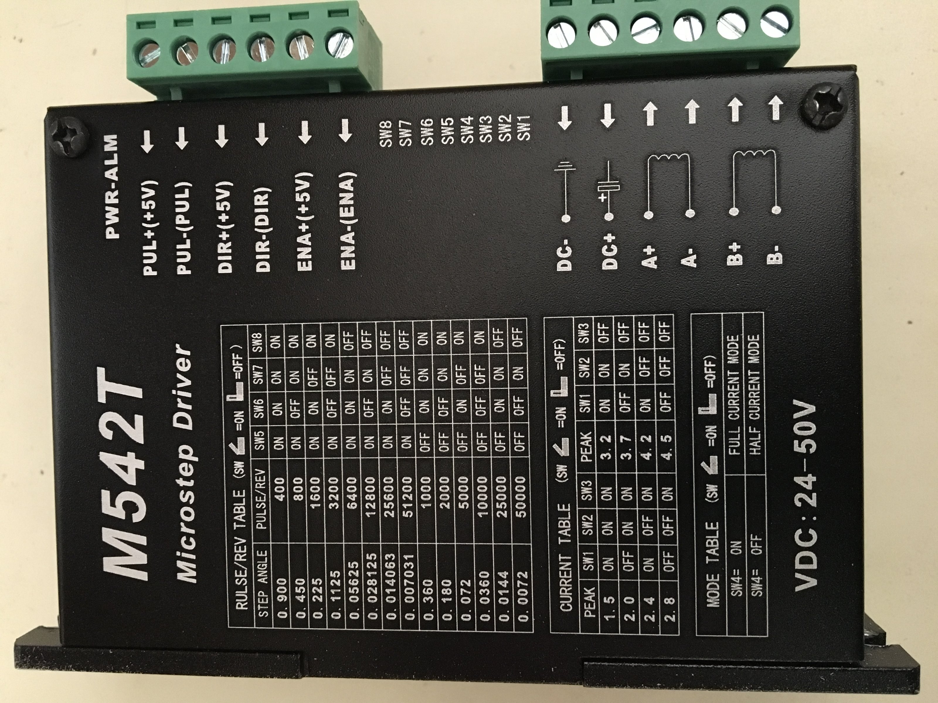
If anyone can tell if the USB is for power or not, that would be helpful. I don't think it is because you can see power supply on the top left corner of the front of the board, On the back it is showing on the top right side. You can also see all the marking points for termination as I had described earlier. Also attached is the driver and the pin settings I have selected based on best guess from information supplied by the drawing for the stepper motors 35HS45-3504S.
Please Log in or Create an account to join the conversation.
- PCW
-

- Offline
- Moderator
-
Less
More
- Posts: 17991
- Thank you received: 5281
24 Mar 2017 00:20 #90166
by PCW
Replied by PCW on topic Help with M542T driver to Breakout board connections
That is a USB interfaced controller so not compatible with LinuxCNC
(its made specifically for Mach3)
(its made specifically for Mach3)
Please Log in or Create an account to join the conversation.
- weyepx
- Offline
- New Member
-
Less
More
- Posts: 5
- Thank you received: 0
24 Mar 2017 16:01 #90218
by weyepx
Replied by weyepx on topic Help with M542T driver to Breakout board connections
I am looking for any/all assistance in wiring this up.
It confuses me because I don't see where to land the wiring from the drivers to the Breakout Board.
Pllllleeeeeaaaasssseee help.
It confuses me because I don't see where to land the wiring from the drivers to the Breakout Board.
Pllllleeeeeaaaasssseee help.
Please Log in or Create an account to join the conversation.
- PCW
-
- Offline
- Moderator
-
Less
More
- Posts: 17991
- Thank you received: 5281
24 Mar 2017 16:22 - 24 Mar 2017 16:23 #90220
by PCW
Replied by PCW on topic Help with M542T driver to Breakout board connections
That breakout will not work with LinuxCNC so even it you wire the
step/dir outputs to the motor drives you cannot use it with LinuxCNC
LinuxCNC can work with parallel ports and parallel port breakouts
and PCI/EPP/Ethernet interfaces made specifically for LinuxCNC,
but LinuxCNC does not currently work with USB/Ethernet interfaces made for Mach3
(like the USB breakout you show here)
If you want help setting up and wiring the breakout with Mach3, you will likely get more help
at CNCzone or a Mach3 forum
Last edit: 24 Mar 2017 16:23 by PCW.
Please Log in or Create an account to join the conversation.
- tommylight
-
- Away
- Moderator
-
Less
More
- Posts: 21743
- Thank you received: 7430
25 Mar 2017 01:53 #90232
by tommylight
Replied by tommylight on topic Help with M542T driver to Breakout board connections
I already explained how to wire the drives, but here it goes again:
Wire the puls on the drive to the step on the BOB, dir to dir, enable to any othe output, +5V/gnd from BOB to all 3 inputs on the drive that have +5V writen.
You can wire all 3 enable inputs on the drives to one output on the BOB, but in case it does not work, you will have to wire each enable to separate outputs on the BOB.
You will also have to set your BOB for +5V common, not for GND common.
That is it.
Regards,
Tom
Please Log in or Create an account to join the conversation.
- weyepx
- Offline
- New Member
-
Less
More
- Posts: 5
- Thank you received: 0
25 Mar 2017 02:08 #90234
by weyepx
Replied by weyepx on topic Help with M542T driver to Breakout board connections
Thanks, Tom.
I wasn't clear on it on but I think you have explained it for me to give it a shot. Wiring for dummies.
I'll do this and let you know my results.
Thanks again,
Paul
I wasn't clear on it on but I think you have explained it for me to give it a shot. Wiring for dummies.
I'll do this and let you know my results.
Thanks again,
Paul
Please Log in or Create an account to join the conversation.
- weyepx
- Offline
- New Member
-
Less
More
- Posts: 5
- Thank you received: 0
25 Mar 2017 04:49 #90238
by weyepx
Replied by weyepx on topic Help with M542T driver to Breakout board connections
Tom,
I guess I am just stupid because I looked at the instructions you gave but I don't see where to land them.
Example: Wire the PUL's on the drive to the step on the BOB.
Question? Where is the "step" termination on the BOB?
You: dir to dir.
Q: There is DIR+ and DIR- on the driver but the board only has one location marked at the Z to land DIR. There is not any indication which one (DIR+ or DIR-) to that location. If DIR+ lands there, where does DIR- land?
You: enable to any othe output.
Q: This is vague and not sure what outputs to land them. Sorry if its dumb question.
I guess if you could mark up a drawing or advise point to point like my opening showed, that would be awesome!
Thanks,
Paul
Please Log in or Create an account to join the conversation.
Time to create page: 0.205 seconds