Spindle control woes
- andypugh
-

- Offline
- Moderator
-

Less
More
- Posts: 19879
- Thank you received: 4644
16 Nov 2018 13:46 #120834
by andypugh
Replied by andypugh on topic Spindle control woes
What is probably happening here is that something is running away because of a difference in sign.
Check that a positive voltage to the spindle control makes the spindle encoder count up.
What is the pid output when the spindle has run up to speed? Is the PID sending a large _negative_ command? Does a negative command make the spindle run reversed, or does it still run forward?
What might be happening is that the PID has gone into the negative area, where reducing the number (more negative) does not slow the spindle but does in fact speed it up.
Please Log in or Create an account to join the conversation.
- Nitram
-

- Offline
- Elite Member
-

Less
More
- Posts: 210
- Thank you received: 15
16 Nov 2018 13:49 #120836
by Nitram
Replied by Nitram on topic Spindle control woes
Thanks for the quick reply Andy.
As it's quite late will check on that tomorrow and let you know.
Cheers Marty.
As it's quite late will check on that tomorrow and let you know.
Cheers Marty.
Please Log in or Create an account to join the conversation.
- Nitram
-
- Offline
- Elite Member
-
Less
More
- Posts: 210
- Thank you received: 15
19 Nov 2018 09:47 #120982
by Nitram
Replied by Nitram on topic Spindle control woes
Hi Andy.
I've taken a look at HAL WATCH and seen that pid.s.output is opposite in sign to either M3 or M4 compared to the commanded speed.
Please see attached HAL WATCH pictures.
I also think I have two problems. Specifically I am having a hard time getting my head around where the hm2_7i76e.0.7i76.0.0.spinout pin should go. Ref the mill I have done in the past with PWM control, the output is a "value" and goes to spindle-output (the pid.s.output) i.e.
net spindle-output => hm2_5i24.0.pwmgen.04.value
whereas spinout is seemingly a commanded RPM value, scaled to the range of the motor/VFD. I am having trouble seeing where exactly into the spindle section of the HAL it should go to make sure it is being correctly influenced by the PID loop. I have tried with hm_2 pin spinout-scalemax either commented out or not. The spindle performs differently, but nothing that represents and form of control.
So, given your earlier post I tried to invert the output of pid.s.output (signal spindle-output) by trying a few things.
1. Put a negative sign before the encoder scale. No change.
2. Use a mult2 and multiply by -1 to see if hm2_7i76e.0.7i76.0.0.spinout would reduce its commanded output to the spindle. With some configurations I got very limited success and the spindle would try to reign itself back but it would always end up overspeeding. Also, the value of hm2_7i76e.0.7i76.0.0.spinout would only ever increase steadily, never decrease to reign in the spindle RPM. That said through, it would increase, but the spindle speed would hunt and try to reign itself back in but would ultimately overspeed.
3. Tried to mult2 x60 the pid.s.output (to change the output to RPM) and net it back into hm2_7i76e.0.7i76.0.0.spinout. Again, no luck.
The idea of the pid command going into the negative looks like it does manifest itself as some of the HAL WATCH attachments will hopefully show. Also shown is the constant increasing of hm2_7i76e.0.7i76.0.0.spinout. Is this pin not the primary pin which commands the spindle? In my case the VFD connects to the 7i76e via the psuedo potentiometer spindle control on the card.
Lastly, and not sure if there is any relationship, but from the bottom of the watch window, the spinout-scalemax was set at 100. I have no idea where that came from? The only way to circumvent that was to un-comment the original spinout-scalemax line in the HAL file. Similarly the .ini file has no reference to a scalemax of 100??
setp hm2_7i76e.0.7i76.0.0.spinout-scalemax 2500
setp hm2_7i76e.0.7i76.0.0.spinout-maxlim 2000
setp hm2_7i76e.0.7i76.0.0.spinout-minlim 50
OK, I better go call it a day... I've spent 11 hours on messing with this one issue, I'm pooped...
Thanks again!!!!
Please Log in or Create an account to join the conversation.
- andypugh
-
- Offline
- Moderator
-
Less
More
- Posts: 19879
- Thank you received: 4644
19 Nov 2018 13:49 #120990
by andypugh
Replied by andypugh on topic Spindle control woes
What is happening here is quite interesting, and not all that uncommon.
For whatever reason the initial spindle speed is a little higher than the requested, and the PID component is reducing its output to bring the speed down.
Unfortunately, once the PID output is negative the spindle drive continues to run positive, and there is a miss-match in sign between pid output and pid feedback, causing a runaway.
Does your spindle actually have the ability to run in reverse? With those outputs the spindle should be running backwards (at 22,000 rpm!)
It would be nice if pid had a "minoutput" setting to prevent it from going in to the negative region, though that is normally not needed for most pid loops.
If your spindle ran in reverse for negative commands then the problem you are seeing would not happen.
The sserial docs should answer your second question, and provide a solution to the problem that you are seeing.
linuxcnc.org/docs/2.7/html/man/man9/sserial.9.html
(say "should" as the wording is a little vague and confused)
...scalemax is the input value that leads to maximum output value. So if full-scale spindle speed is 2500 rpm then you might want to set the scalemax to that.
It is _probably_ easier to work in revs-per-second throughout, though.
(To answer another question, scalemax defaults to 100, you definitely do want to set in the HAL file to the correct value)
So, set the scalemax to the maximum _spindle_ revs-per-second (you earlier said that the max _motor_ rpm was 2500? That would be 41.7 rps) Where is the encoder?)
Then set the spinout-maxlim to +41.7 but set the spinout-minlim to 0 (or, possibly, some positive value). That means that if the pid goes negative then the dive sees zero speed, rather than a large control voltage corresponding to a negative speed.
Please Log in or Create an account to join the conversation.
- Nitram
-
- Offline
- Elite Member
-
Less
More
- Posts: 210
- Thank you received: 15
21 Nov 2018 11:07 #121113
by Nitram
Replied by Nitram on topic Spindle control woes
Thanks with all you insight on this Andy.
In short, a negative command does not run the vfd in reverse after initial establishment of sign for direction. As the 7i76e spindle output is an analogue wiper signal it can never be less than zero, with direction ultimately being commanded by the direction pin.
I have a few things I would like to check as well, specifically why the feedback velocity is jumping around like it does. I wonder whether I have an index-enable signal/pin hard set true somewhere causing the velocity to reset to zero each turn making the velocity algorithm jump around causing unneccesay fluctuations.
I would also like to explore a limit2 on the pid/spinout output to keep it positive.
Interestingly I think that a negative command i.e. S500M4 shows up as -500 on the gmoccapy screen, but if the spindle is direction is already established running off an m3 command, anything negative will not reverse direction again mainly because I suspect that direction is set initially with the direction pin and thereafter velocity is simply controlled via the analogue signal which itself can not be negative.
IIRC limiting minlim to a slightly positive value rather that mirroring maxlim but as a negative figure prevents an m4 being executed. In other words, it seems the command needs to see and respond to the negative in the command in the initial instance, but thereafter can only control the velocity of the m4 via a 0 to 5v signal (in absolute terms). Similarly for an m3 command. The initial positive output confirms direction (m3) and thereafter the actual rps is solely controlled by the 0-5v signal. In other words a pid commanded negative signal after the initial direction has been established does not seemingly change direction.
Similarly while I would like to try it, I therefore have my doubts about a limit2 function locking the commands to the positive (greater then zero) side being an answer. Without an initial negative command (m4) as the initial output to establish the direction pin, an m4 could never be executed.
Buuut perhaps I'm reading waaay too much into it?
Thanks again Andy and moreover thanks for sticking with this most verbose post")
In short, a negative command does not run the vfd in reverse after initial establishment of sign for direction. As the 7i76e spindle output is an analogue wiper signal it can never be less than zero, with direction ultimately being commanded by the direction pin.
I have a few things I would like to check as well, specifically why the feedback velocity is jumping around like it does. I wonder whether I have an index-enable signal/pin hard set true somewhere causing the velocity to reset to zero each turn making the velocity algorithm jump around causing unneccesay fluctuations.
I would also like to explore a limit2 on the pid/spinout output to keep it positive.
Interestingly I think that a negative command i.e. S500M4 shows up as -500 on the gmoccapy screen, but if the spindle is direction is already established running off an m3 command, anything negative will not reverse direction again mainly because I suspect that direction is set initially with the direction pin and thereafter velocity is simply controlled via the analogue signal which itself can not be negative.
IIRC limiting minlim to a slightly positive value rather that mirroring maxlim but as a negative figure prevents an m4 being executed. In other words, it seems the command needs to see and respond to the negative in the command in the initial instance, but thereafter can only control the velocity of the m4 via a 0 to 5v signal (in absolute terms). Similarly for an m3 command. The initial positive output confirms direction (m3) and thereafter the actual rps is solely controlled by the 0-5v signal. In other words a pid commanded negative signal after the initial direction has been established does not seemingly change direction.
Similarly while I would like to try it, I therefore have my doubts about a limit2 function locking the commands to the positive (greater then zero) side being an answer. Without an initial negative command (m4) as the initial output to establish the direction pin, an m4 could never be executed.
Buuut perhaps I'm reading waaay too much into it?
Thanks again Andy and moreover thanks for sticking with this most verbose post
Please Log in or Create an account to join the conversation.
- andypugh
-
- Offline
- Moderator
-
Less
More
- Posts: 19879
- Thank you received: 4644
21 Nov 2018 12:31 #121116
by andypugh
Replied by andypugh on topic Spindle control woes
OK, so you are saying that the problem lies with your spindle drive, in that it doesn't respond to a direction command once it has started?
Is this configurable? It's not a great feature, and might make rigid tapping impossible. Perhaps this is a configuration setting in the drive?
There are ways to work round this in HAL, I feel sure.
My first idea would have been to use a pair of mux2 to set the limits of a limit1, but that won't work as the limit1 limits are parameters not pins.
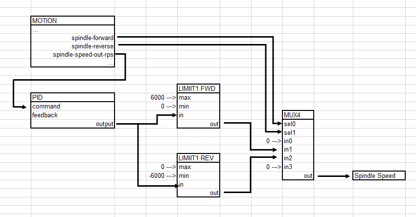
So the answer is probably to use two limit1 components, one for forward and one for reverse then choose between them using a mux2.
In fact it might be better to use a mux4. Then connect sel0 to spindle-fwd and sel1 to spindle-rev. That means that you can setp the output to zero on the unused (0 and 3) outputs too.
Is this configurable? It's not a great feature, and might make rigid tapping impossible. Perhaps this is a configuration setting in the drive?
There are ways to work round this in HAL, I feel sure.
My first idea would have been to use a pair of mux2 to set the limits of a limit1, but that won't work as the limit1 limits are parameters not pins.
So the answer is probably to use two limit1 components, one for forward and one for reverse then choose between them using a mux2.
In fact it might be better to use a mux4. Then connect sel0 to spindle-fwd and sel1 to spindle-rev. That means that you can setp the output to zero on the unused (0 and 3) outputs too.
Please Log in or Create an account to join the conversation.
- Mike_Eitel
-

- Offline
- Platinum Member
-

Less
More
- Posts: 1052
- Thank you received: 183
22 Nov 2018 16:17 #121221
by Mike_Eitel
Replied by Mike_Eitel on topic Spindle control woes
I have similar expirience. Means that a change of the direction Input is not regarded after a start by Enable. Solution is some ladder that takes away time the Enable signal for short time when any change in direction occours.
Please Log in or Create an account to join the conversation.
- andypugh
-
- Offline
- Moderator
-
Less
More
- Posts: 19879
- Thank you received: 4644
22 Nov 2018 17:37 #121225
by andypugh
Ladder can, of course, be used for this, but there are other ways too.
1) Use a three-way AND to allow the enable to be masked (using the "logic" component)
linuxcnc.org/docs/2.7/html/man/man9/logic.9.html
2) use a pair of edge detectors to detect a rising edge on spindle-fwd and spindle-rev and use the output to mask the
linuxcnc.org/docs/2.7/html/man/man9/edge.9.html
Some tweaking of these signal names will be needed to suit existing signals being re-used and existing signals being over-written
Replied by andypugh on topic Spindle control woes
I have similar expirience. Means that a change of the direction Input is not regarded after a start by Enable. Solution is some ladder that takes away time the Enable signal for short time when any change in direction occours.
Ladder can, of course, be used for this, but there are other ways too.
1) Use a three-way AND to allow the enable to be masked (using the "logic" component)
linuxcnc.org/docs/2.7/html/man/man9/logic.9.html
2) use a pair of edge detectors to detect a rising edge on spindle-fwd and spindle-rev and use the output to mask the
linuxcnc.org/docs/2.7/html/man/man9/edge.9.html
Some tweaking of these signal names will be needed to suit existing signals being re-used and existing signals being over-written
loadrt logic  personality = 259
loadrt edge count=2
...
addf edge.0   servo-thread
addf edge.1   servo-thread
addf logic.0  servo-thread
...
net spindle-fwd edge.0.in
net spindle-rev edge.1.in
# Detect rising edges
setp edge.0.in-edge 0
setp edge.1.in-edge 0
# set to give a 500mS pulse
setp edge.0.out-width-ns 500000
setp edge.1.out-width-ns 500000
#connect the three-way AND
net spindle-on => logic.0.in-00
net fwd-mask edge.0.out-invert => logic.0.in-01
net rev-mask edge.2.out-invert => logic.0.in-02
#connect this to where the spindle-enable currently goes
net spindle-enable-masked  logic.0.and => hm2_7i92.7i77.0.1.spinena
Please Log in or Create an account to join the conversation.
- Mike_Eitel
-
- Offline
- Platinum Member
-
Less
More
- Posts: 1052
- Thank you received: 183
22 Nov 2018 19:02 #121228
by Mike_Eitel
Replied by Mike_Eitel on topic Spindle control woes
Totally agree
Just doing some more functionalities in CL, so it was easy.
Just doing some more functionalities in CL, so it was easy.
Please Log in or Create an account to join the conversation.
- Nitram
-
- Offline
- Elite Member
-
Less
More
- Posts: 210
- Thank you received: 15
06 Dec 2018 02:43 - 06 Dec 2018 02:59 #121918
by Nitram
Replied by Nitram on topic Spindle control woes
Thanks to everyone's help on this!
Andy, I have gone back and got the spindle working properly and wanted to get on record what I did for others to reference.
Specifically, the vfd is a chinese hy model.
Here is the distilled down version, in conjunction with the symptoms as laid out in previous posts of this thread, I hope it may help someone.
First part of the solution was to get the scaling right. My motor ran at max RPM (full scale) at 75 Hz. Therefore I set the scaling to 75 as follows:
setp hm2_7i76e.0.7i76.0.0.spinout-scalemax 75
setp hm2_7i76e.0.7i76.0.0.spinout-maxlim 75
setp hm2_7i76e.0.7i76.0.0.spinout-minlim -75
Secondly, I initially started with some very low level PID values, ultimately finishing on:
P = 0.25
I = 2.5
D = 0.0
FF0 = 0.0
FF1 = 0
FF2 = 0
The final fix was in relation to having the pid loop give contra signs to the direction of rotation. In other words, causing a runaway condition rather than a return to target condition. As mentioned above, once the initial directional command (M3 or M4) had been sent and established via sign (+ for M3, - for M4), then dragging the pid command into the contra sign region did not fix the divergence. IOW an overspeed of a +300RPM command could not be corrected by a -???RPM command. Rather it must simply have a smaller value of the same sign to drag the speed back down. IOW, given that the VFD is driven from the 7i76e via a pseudo potentiometer (in this case 0-5V) arrangement, the output can only ever be positive with the direction being controlled by a separate pin i.e. it is not a "zero in the middle" controller, which can go equal amounts into negative and positive to control BOTH speed AND direction.
So to overcome this, the solution which worked for me was to use absolutes of the speed command and feedback thus:
net spindle-index-enable <=> pid.s.index-enable
net spindle-enable => pid.s.enable
net spindle-vel-cmd-rps-abs => pid.s.command
net spindle-vel-fb-rps-abs => pid.s.feedback
net spindle-output <= pid.s.output
and then of course, having the spindle speed command pin (spinout pin) connected to and thus ultimately controlled by the pid.s.output pin ("spindle-output" signal from above) thus:
net spindle-output hm2_7i76e.0.7i76.0.0.spinout
On a slightly different note, my spindle encoder is a pair of photo-interrupters, one for index, one for phase a, and thus with the encoder set to count mode. In this case feedback was giving a negative increasing value of position:
net spindle-revs <= hm2_7i76e.0.encoder.04.position
i.e. "spindle-revs" was counting into the negatives.
Thus I changed the sign of the encoder scale in the .ini file to facilitate the encoder counting up. This then enabled all the spindle synchronized functionality, as the controller was initially not seeing an increase (increasing positive value) in spindle position.
Again, I really hope that taking the time to document this may help someone in the future, and as always thanks for everyone's ongoing help and especially thanks to Andy for your ongoing advice.
Kind regards,
Marty.
Last edit: 06 Dec 2018 02:59 by Nitram.
Please Log in or Create an account to join the conversation.
Time to create page: 0.102 seconds