How to Control Digital Outputs
- MattMethods
- Offline
- New Member
-

Less
More
- Posts: 8
- Thank you received: 0
05 Dec 2017 06:36 #102691
by MattMethods
How to Control Digital Outputs was created by MattMethods
Hi guys,
I'm still relatively new to LinuxCNC.
I'm currently using a leadshine mx3660 driver to control three stepper motors for a university project.
Ideally I want the ability to automatically take a photo of the progress of the experiment after each iteration.
The electronics guy at uni has wired up a FET switching system that closes a switch when a voltage is applied to the input. He tested it with an arbitrary power supply, and it was able to take photos with a camera with no issue.
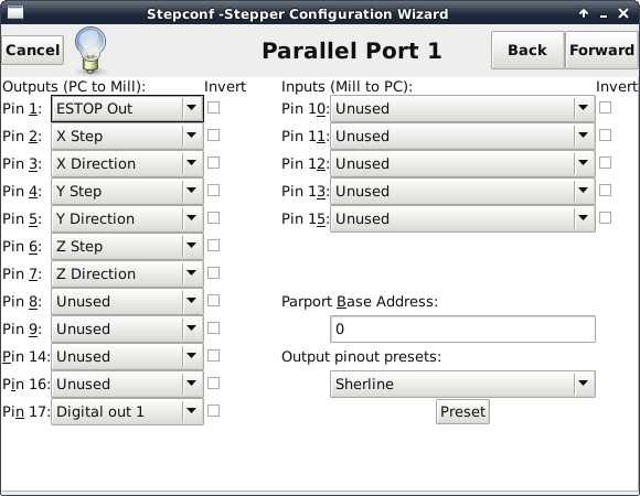
However, I have currently been unable to operate this device with the digital outputs on the leadshine mx3660. I have selected digital out 1 for pin 17 in the stepconf wizard, as seen in the photo, which is connected to output 1 according to the driver manual.
In the .hal file, it even has the following lines:
net dout-01 <= motion.digital-out-01
net dout-01 => parport.0.pin-17-out
I was using this G-code to operate it:
G4 P1
M64 P1
G4 P0.3
M63 P1
However this has not worked.
The switch has an LED light as well which should light up when a voltage is applied to it, so I have used the following G-code to test it as well to no avail
G4 P1
M64 P1
G4 P10
M65 P1
Is there something obvious that I'm missing to be running the digital output? Because I'm not sure of what else to do to make sure the M64/65 codes work.
It is worth noting that when I hit run for the first time, I did hear the camera shutter when the motors started (not when it was programmed to), but it did not take a photo as it had in the past. So there is the potential that the box is broken too, but I wanted to check I had all the programing correct to begin with. I will be checking with the electronics guy tomorrow whether there is an issue with the box.
Any help will be really appreciated! If there's anything I've left out, please shoot")
I'm still relatively new to LinuxCNC.
I'm currently using a leadshine mx3660 driver to control three stepper motors for a university project.
Ideally I want the ability to automatically take a photo of the progress of the experiment after each iteration.
The electronics guy at uni has wired up a FET switching system that closes a switch when a voltage is applied to the input. He tested it with an arbitrary power supply, and it was able to take photos with a camera with no issue.
However, I have currently been unable to operate this device with the digital outputs on the leadshine mx3660. I have selected digital out 1 for pin 17 in the stepconf wizard, as seen in the photo, which is connected to output 1 according to the driver manual.
In the .hal file, it even has the following lines:
net dout-01 <= motion.digital-out-01
net dout-01 => parport.0.pin-17-out
I was using this G-code to operate it:
G4 P1
M64 P1
G4 P0.3
M63 P1
However this has not worked.
The switch has an LED light as well which should light up when a voltage is applied to it, so I have used the following G-code to test it as well to no avail
G4 P1
M64 P1
G4 P10
M65 P1
Is there something obvious that I'm missing to be running the digital output? Because I'm not sure of what else to do to make sure the M64/65 codes work.
It is worth noting that when I hit run for the first time, I did hear the camera shutter when the motors started (not when it was programmed to), but it did not take a photo as it had in the past. So there is the potential that the box is broken too, but I wanted to check I had all the programing correct to begin with. I will be checking with the electronics guy tomorrow whether there is an issue with the box.
Any help will be really appreciated! If there's anything I've left out, please shoot
Please Log in or Create an account to join the conversation.
- BigJohnT
-

- Offline
- Administrator
-

Less
More
- Posts: 3990
- Thank you received: 994
05 Dec 2017 11:59 #102693
by BigJohnT
Replied by BigJohnT on topic How to Control Digital Outputs
Open the "Show Hal Configuration" app and add your pins to the watch window. After turning on and homing just do a M64 P1 in the MDI tab and see if your pins change state. Could be a hardware issue...
JT
JT
Please Log in or Create an account to join the conversation.
- MattMethods
- Offline
- New Member
-
Less
More
- Posts: 8
- Thank you received: 0
05 Dec 2017 23:59 #102710
by MattMethods
Replied by MattMethods on topic How to Control Digital Outputs
In the watch window the LED turns yellow when I run the M64 P1 command, which from what I gather represents the value as true? I did also add the digital out 0-3 pins in the watch space and ran the same commands and they also turned yellow as well, which I'm assuming isn't anything special?
Please Log in or Create an account to join the conversation.
- ozzyrob
-

- Visitor
-

06 Dec 2017 00:12 #102711
by ozzyrob
Replied by ozzyrob on topic How to Control Digital Outputs
I'd check that the physical output pin turns on & off on the mx3660 without the camera do-dad connected.
You have connected the pin from the mx3660 and GND to the camera do-dad ?
You have connected the pin from the mx3660 and GND to the camera do-dad ?
Please Log in or Create an account to join the conversation.
- MattMethods
- Offline
- New Member
-
Less
More
- Posts: 8
- Thank you received: 0
06 Dec 2017 00:22 #102712
by MattMethods
Replied by MattMethods on topic How to Control Digital Outputs
I'm currently checking the output pins on the mx3660 with a multimeter and the output pins are all reading 0V. (I reset up the configuration so digital out 0-3 corresponded to output 1-4, and used the m64 p0-3 commands individually in the MDI command window).
Should I check the actual pins on the db25 cable?
Should I check the actual pins on the db25 cable?
Please Log in or Create an account to join the conversation.
- MattMethods
- Offline
- New Member
-
Less
More
- Posts: 8
- Thank you received: 0
06 Dec 2017 01:31 - 06 Dec 2017 02:57 #102714
by MattMethods
Replied by MattMethods on topic How to Control Digital Outputs
So we've checked the pins on the db25 cable and they are showing 3.3v on the respective pins and we have been able to turn that on and off within LinuxCNC, so that suggests that it's actually an issue with the leadshine mx3660 driver. So the Electronics guy is going to have a bit of a play with the driver to see how he goes.
Thanks heaps for the help guys!
EDIT: We have managed to figure out the problem and it is all working. Thanks heaps again!
Thanks heaps for the help guys!
EDIT: We have managed to figure out the problem and it is all working. Thanks heaps again!
Last edit: 06 Dec 2017 02:57 by MattMethods.
Please Log in or Create an account to join the conversation.
- BigJohnT
-
- Offline
- Administrator
-
Less
More
- Posts: 3990
- Thank you received: 994
06 Dec 2017 15:17 #102720
by BigJohnT
Replied by BigJohnT on topic How to Control Digital Outputs
What was the problem?
JT
JT
Please Log in or Create an account to join the conversation.
- MattMethods
- Offline
- New Member
-
Less
More
- Posts: 8
- Thank you received: 0
06 Dec 2017 20:35 #102731
by MattMethods
Replied by MattMethods on topic How to Control Digital Outputs
I actually feel like a bit of an idiot... but the digital output didn't actually supply any power, it's just an electronic relay. Which in hindsight makes a lot of sense.
The manual didn't make it clear that it was just an electronic relay, but I'm assuming that might be commonplace with stepper motor drivers and I was just simply unaware of that through lack of experience.
The funny thing is that the reason we made the FET switching system was because we thought that the output actually output a digital signal, rather than being an electronic relay, so we could have realistically just used the driver outputs to control the circuit to take a photo rather than making up a box for it. But that's all part of the fun haha.
Please Log in or Create an account to join the conversation.
- BigJohnT
-
- Offline
- Administrator
-
Less
More
- Posts: 3990
- Thank you received: 994
06 Dec 2017 20:51 #102732
by BigJohnT
Replied by BigJohnT on topic How to Control Digital Outputs
Don't feel bad about learning and possibly helping someone else in the future when they read this thread.
JT
JT
Please Log in or Create an account to join the conversation.
Time to create page: 0.220 seconds