Reading a tachometer signal
- JohnnyCNC
-
 Topic Author
- Offline
- Platinum Member
-

Less
More
- Posts: 570
- Thank you received: 111
20 Feb 2018 00:38 #106197
by JohnnyCNC
Reading a tachometer signal was created by JohnnyCNC
I am trying to get a tachometer connected via a 7i76. Anyone have any idea what I am doing wrong?
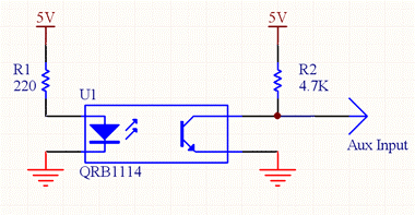
I have an optical reflective tachometer that I built using the circuit below except that I used a OPB704WZ sensor instead of the QRB1114. This unit works on my DRO. I thought that it might work if I connected it to encoder. I am thinking that there is probably something in the HAL or .INI that is not right but I don’t know what that might be.
TB3 - 9 Ground
TB3 - 12 +5 volts (4.91 measured)
TB3 - 13 Index+ (Aux Input on diagram)
Jumpers W4,W4, & W6 are in the left hand position for TTL single ended input.
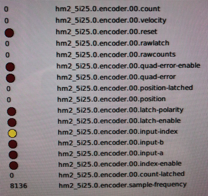
This is what the HAL watch shows when the spindle is running.
Thanks
John
Please Log in or Create an account to join the conversation.
- PCW
-

- Offline
- Moderator
-

Less
More
- Posts: 17657
- Thank you received: 5164
20 Feb 2018 00:51 #106199
by PCW
Replied by PCW on topic Reading a tachometer signal
Does the hm2_5i25.0.input-index toggle when you rotate the spindle?
If not, what are the voltage levels on the AUX pin for both sensor states?
If not, what are the voltage levels on the AUX pin for both sensor states?
Please Log in or Create an account to join the conversation.
- JohnnyCNC
-
 Topic Author
- Offline
- Platinum Member
-

Less
More
- Posts: 570
- Thank you received: 111
20 Feb 2018 02:02 #106200
by JohnnyCNC
Replied by JohnnyCNC on topic Reading a tachometer signal
No, hm2_5i25.0.input-index does not toggle.
4.65 and 2.11 volts
4.65 and 2.11 volts
Please Log in or Create an account to join the conversation.
- PCW
-

- Offline
- Moderator
-

Less
More
- Posts: 17657
- Thank you received: 5164
20 Feb 2018 03:22 #106205
by PCW
Replied by PCW on topic Reading a tachometer signal
Right, so that is not going to work because the low level (2.11 V) is not a valid TTL low level
Part of the problem is that the 7I76 input has a 2K pullup so the pullup current is higher than expected
things to try:
1. Remove the 4.7K pullup
2. increase the LED current (its ~15 mA with the 220 Ohm resistor) you could safely double it to 30 mA or so
with a 100 Ohm resistor.
3. Make sure the optical target distance/angle is correct (adjust while reading the low state voltage)
Please Log in or Create an account to join the conversation.
- JohnnyCNC
-
 Topic Author
- Offline
- Platinum Member
-

Less
More
- Posts: 570
- Thank you received: 111
20 Feb 2018 03:34 #106206
by JohnnyCNC
Replied by JohnnyCNC on topic Reading a tachometer signal
Thanks PCW.
I'll give that a try.
John
I'll give that a try.
John
Please Log in or Create an account to join the conversation.
- JohnnyCNC
-
 Topic Author
- Offline
- Platinum Member
-

Less
More
- Posts: 570
- Thank you received: 111
23 Feb 2018 00:26 #106362
by JohnnyCNC
Replied by JohnnyCNC on topic Reading a tachometer signal
I made another sensor with the changes PCW recommended and the hm2_5i25.0.input-index pin now toggles when I rotate the spindle. Now to get this hooked to the display and fed into the PID to make sure the commanded speed is achieved.
Thanks PCW
John
Thanks PCW
John
Please Log in or Create an account to join the conversation.
- PCW
-

- Offline
- Moderator
-

Less
More
- Posts: 17657
- Thank you received: 5164
23 Feb 2018 00:31 #106364
by PCW
Replied by PCW on topic Reading a tachometer signal
Note that if you expect to read RPM you will need to connect the input to the "A" input
Is it really an index? (one pulse per turn)
Is it really an index? (one pulse per turn)
Please Log in or Create an account to join the conversation.
- JohnnyCNC
-
 Topic Author
- Offline
- Platinum Member
-

Less
More
- Posts: 570
- Thank you received: 111
23 Feb 2018 00:46 #106365
by JohnnyCNC
Replied by JohnnyCNC on topic Reading a tachometer signal
Right now it is one pulse per turn but at this moments I just want to count RPM. But reading what you just said and thinking farther ahead, since I'm not really looking for an index hooking it to the A input with allow the raw counts to be converted to RPM where as the index input would not. Is that correct?
Thanks
John
Thanks
John
Please Log in or Create an account to join the conversation.
- PCW
-

- Offline
- Moderator
-

Less
More
- Posts: 17657
- Thank you received: 5164
23 Feb 2018 15:32 #106394
by PCW
Replied by PCW on topic Reading a tachometer signal
Yes, if you connect the sensor to the 'A' encoder input you can read the spindle RPM
you will also need to set the encoder counter mode to 1
(the default counter mode is quadrature =0 which will not count with a single input)
you will also need to set the encoder counter mode to 1
(the default counter mode is quadrature =0 which will not count with a single input)
Please Log in or Create an account to join the conversation.
- JohnnyCNC
-
 Topic Author
- Offline
- Platinum Member
-

Less
More
- Posts: 570
- Thank you received: 111
27 Feb 2018 01:51 #106596
by JohnnyCNC
Replied by JohnnyCNC on topic Reading a tachometer signal
Just a follow up to this PCW. I did get this all working with you suggestions. I dropped the 4.7K resistor and replaced the 220 ohm with a 100 ohm. Works great now.
Thank You.
John
Thank You.
John
Please Log in or Create an account to join the conversation.
Time to create page: 0.125 seconds


