MESA 6i25 and 7i76D PNCCONFIG Issues
- Askjerry
-
 Topic Author
- Offline
- Elite Member
-

- Posts: 239
- Thank you received: 31
The 7i76D has 6 terminal strips attached... and I'm having some issues with getting pins configured properly...
In PNCCONFIG it references the step generators as 0 through 4... and I can see that this spans TB2 and TB3 of the actual 7i76D card.
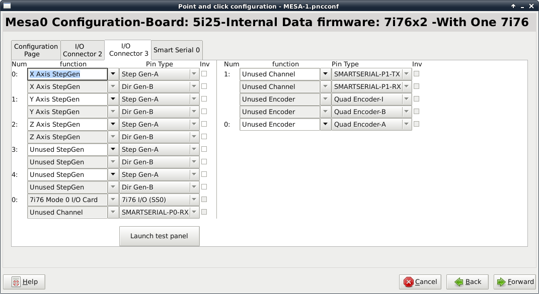
I understand that... it's odd... but I can set up the X / Y / Z just fine.
Now TB5 and TB6 are set up for a bunch of inputs and outputs... very useful for things like ESTOP-IN for example.
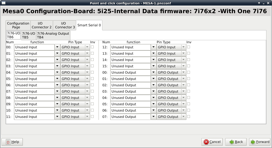
If I don't specify anything... it runs just fine... signals working, etc.

As you can see above... it shows the terminal strips... in this case TB6. But... here is the thing... if I go to TB6, PIN-00 and select ESTOP-IN... it saves it just fine. I would expect to run the machine, apply signal, and get ESTOP results.
But if I try to actually run that configuration... it fails...
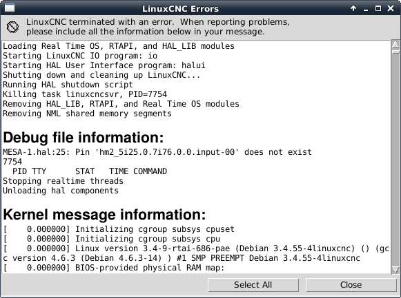
So what is going on? Why won't it let me connect a pin that is clearly on the board???
Thanks,
Jerry
Please Log in or Create an account to join the conversation.
- cmorley
- Away
- Moderator
-

- Posts: 7343
- Thank you received: 2164
The I/O pins won't be available if field power is missing.
Chris M
Please Log in or Create an account to join the conversation.
- andypugh
-

- Offline
- Moderator
-
- Posts: 19886
- Thank you received: 4645
Please Log in or Create an account to join the conversation.
- Askjerry
-
Topic Author
- Offline
- Elite Member
-
- Posts: 239
- Thank you received: 31
Per the conversation with MESA, I set the 6i25 board to have the W1 and W2 settings to the UP position where the board would supply power. After I did that, the yellow LED illuminated showing power. Do I need to install a jumper from one of the 5v pins to one of the field power pins? I didn't see any documentation about that... I thought the FPGA board (6i25) would supply the power to the board.
Are you saying that I MUST set the 6i25 board to DISABLE the power, then connect a separate power supply to the 7i76D?
I was hoping that I could just power the board from the PC... is this not possible???
Jerry
Please Log in or Create an account to join the conversation.
- PCW
-

- Online
- Moderator
-
- Posts: 17996
- Thank you received: 5282
Both power sources must be present for the 7I76/7I76D digital I/O to be found
Please Log in or Create an account to join the conversation.
- Askjerry
-
Topic Author
- Offline
- Elite Member
-
- Posts: 239
- Thank you received: 31
I was under the opinion that when the jumper was set to get the 5v power from the PC, that it negated the need for the 12v supply.
To be clear... I should still have the jumpers set as described above or not?
And is there a reason I would prefer a 12v supply over a 24v supply or vice versa?
I want to get this thing to work... and I want to avoid blowing the power supply. Does anyone have a proper diagram and/or switch setting? Hard to believe a manufacturer wouldn't include more details like this. (I guess my video series will be the first to really go into this detail... because I have not found it yet.)
By the way... I appreciate the help very much. Once I figure it all out (with your help) I'll make the detailed instructions so the next person won't have to repeat my steps. If you do know of better documentation and/or video... please link below.
Thanks,
Jerry
Please Log in or Create an account to join the conversation.
- Askjerry
-
Topic Author
- Offline
- Elite Member
-
- Posts: 239
- Thank you received: 31
So if that is true... then I should set the 6i25 W1 and W2 to DOWN to isolate logic power from the PC... and connect a 12 or 24v supply on the 7i76D from TB-1, PIN-1 (VFIELD IN) and TB-1, PIN-8 (GROUND) .
This should then supply all the logic power as well as providing 12v or 24v to power any relays, induction sensors, etc.
Correct??
This would mean that if anyone expects to use ANY of the pins on TB-5 and/or TB-6, they MUST have an external supply connected.
Correct?
Please Log in or Create an account to join the conversation.
- andypugh
-
- Offline
- Moderator
-
- Posts: 19886
- Thank you received: 4645
After looking at it more closely... it looks like the setting for a single power supply (7i78D W1 = Left) Ties the VIN together with FIELD POWER. If I read it correctly... when this is done AND an 8v to 32v DC supply is connected... the board creates it's own 5vcd logic supply.
So if that is true... then I should set the 6i25 W1 and W2 to DOWN to isolate logic power from the PC
Yes, and I think that last part is quite important.
Yes. But then would you really expect to power your limit switches from FPGA card cable power?This would mean that if anyone expects to use ANY of the pins on TB-5 and/or TB-6, they MUST have an external supply connected.
Correct?
Please Log in or Create an account to join the conversation.
- PCW
-
- Online
- Moderator
-
- Posts: 17996
- Thank you received: 5282
The field power is completely isolated and independent of 5V logic power
Please Log in or Create an account to join the conversation.
- Askjerry
-
Topic Author
- Offline
- Elite Member
-
- Posts: 239
- Thank you received: 31
There is 5v power which can come from EITHER TB-1 PIN-3 OR it can come from the PC (FBGA card).
As I simply want 5v from the PC... no real load on it... I'm only running the stepper driver optocouplers...
1) The 7i76D W1 would be set LEFT to specify a single supply for the TB-4, TB-5, and TB-6
2) The 7i76d W2 would be set LEFT to specify that an EXTERNAL 5v supply is NOT used, meaning that the 6i25 is the supply.
3) The 6i25 W1 and W2 would be placed UP to supply 5v logic power.
After reading again... I see that the warning is saying simply, "IF using EXTERNAL 5v, DO NOT use the 6i25 power."
It was that "single supply" statement that was throwing me... I was thinking the PC 5v supply was #1, and the 12 (or 24) volt supply was #2. I get it now... so I'll purchase a 12v supply, and set the jumpers for...
6i25 - W1 UP (Supply power), W2 UP (Supply power)
7i76D - W1 LEFT (Single supply) W2 LEFT (Use 6i25 for 5v source up to 1A)
Unless anyone says no... that's the plan.
Thanks,
Jerry
Please Log in or Create an account to join the conversation.