Losing my mind with servo pid tuning
- alan_3301
- Offline
- Premium Member
-

Less
More
- Posts: 136
- Thank you received: 22
28 Oct 2018 23:36 - 28 Oct 2018 23:38 #119577
by alan_3301
Losing my mind with servo pid tuning was created by alan_3301
I thought I was making some progress in the past few days, but I am at the point where I don't think I can figure this out. Sorry for the information overload, but hopefully there is something here that can help figure this out.
Edit - I have to stop myself because I would continue writing forever. In summary I have two questions:
Is it likely the driver is poorly tuned? When is it appropriate to set FF1=1, or FF1=(10 / OUTPUT_SCALE)? (or something completely different?
This is a lathe with delta 400w servos on X and Z, and a 1kw servo driving the spindle, which is also setup as a c axis in hal. All 3 drives have been tuned with the delta software. It estimates motor/load ratio, you tell it the bandwidth and it writes the results for internal gains for the drive. The drives connect to a 5i25 and 7i77 to linuxcnc.
Machine units are inches for X and Z, and degrees for C.
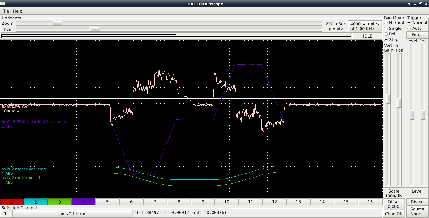
For reference, the X and Z drives are set up to output 5000 PPR (20,000 encoder counts per rev) They drive a 5mm lead ballscrew. 1 inch = 5.08 revolutions = 101,600 counts. Being that the axis max speed is ~9.8425 inches/s @ 3000 rpm (50 rps) @ 10V, I have set OUTPUT_SCALE = -9.842519685, so that FF1=1. Everything is working perfectly on the linear axes (X and Z). I have attached a halscope screenshot of a 210 ipm Z axis jog moving about 0.8 inches, then back to 0. As far as I can tell, the f-error is never more than 0.0002 inches. This seems perfect, and all I had to do was adjust P for maximum stiffness without oscillation. That turned out to be a P of 500. Is it supposed to be this easy?
I was able to tune the spindle pid fairly easily. The actual speed matches the commanded within 5-10 rpms from 50 - 1500 rpms.
It does not matchperfectly below 50 rpms, but I am ok with that. Here's the spindle settings. The analogout-scalemax and min/maxlim settings are read from the C axis section in the INI, so all those settings are the same for spindle and C axis.
[SPINDLE_9]
P = -0.00025
I = 0.0
D = 0.0
FF0 = 0.0015
FF1 = 0.0
FF2 = 0.0
BIAS = -0.02
DEADBAND = 0.0
MAX_OUTPUT = 0
The C is what is driving me crazy. The drive is set up to output 9000 PPR (36,000 counts per rev). The motor drives the spindle by timing belt at 2:1. I currently have 2 configs set up. One has the encoder scale and output scale in degrees, the other in revolutions. For my calulations I am accounting for the belt reduction and using the numbers at the spindle.
I have tried many PID values, but currently these the closest I have come. The ferror is always around 10 degrees when stopped, never going close to 0. The servo is not very stiff, and is both twitching in small amounts, and wandering 10-15 degrees. When jogging the axis it only moves slowly while jumping forward small amounts occasionally. Comments are posted here only, not in config
ENCODER_SCALE = 72000 #counts per revolution
OUTPUT_SCALE = 25 #revs per second at 10V (1500 rpm)
P = -0.0015
I = 0.0
D = 0.0
FF0 = 0.0
FF1 = 0.00111111 #lowered to stop jog runaway (overshoots waaay too far) shouldn't it be 1?
FF2 = 0.0
BIAS = -0.0025
DEADBAND = 0.00004
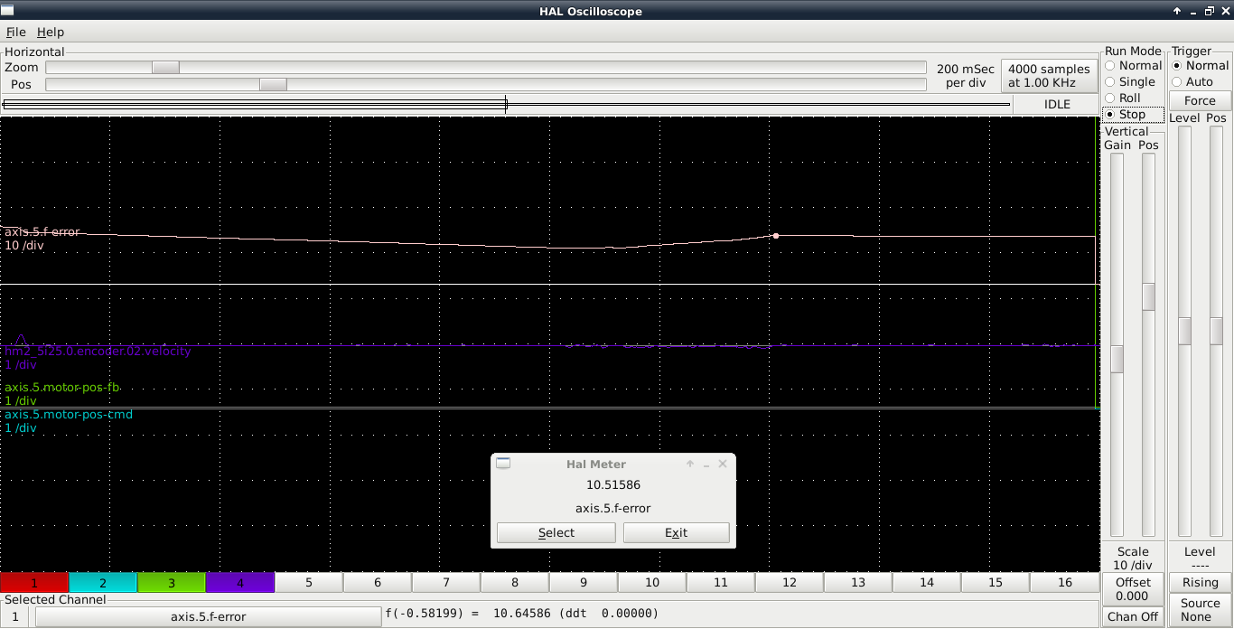
Here is a halscope capture. It's probably not of any use. I'm attempting to jog the C axis, but not much is happening.
I'm confused about what I should set FF1 to be.
From a post here:
From gnipsel.com/linuxcnc/tuning/servo.html
Maybe this is why my X/Z Pgains are so high at 500?
I have also tried switching the 7i77 analog out #5 connection to the #3 (and making the switch in HAL) with the same results.
Edit - I have to stop myself because I would continue writing forever. In summary I have two questions:
Is it likely the driver is poorly tuned? When is it appropriate to set FF1=1, or FF1=(10 / OUTPUT_SCALE)? (or something completely different?
This is a lathe with delta 400w servos on X and Z, and a 1kw servo driving the spindle, which is also setup as a c axis in hal. All 3 drives have been tuned with the delta software. It estimates motor/load ratio, you tell it the bandwidth and it writes the results for internal gains for the drive. The drives connect to a 5i25 and 7i77 to linuxcnc.
Machine units are inches for X and Z, and degrees for C.
For reference, the X and Z drives are set up to output 5000 PPR (20,000 encoder counts per rev) They drive a 5mm lead ballscrew. 1 inch = 5.08 revolutions = 101,600 counts. Being that the axis max speed is ~9.8425 inches/s @ 3000 rpm (50 rps) @ 10V, I have set OUTPUT_SCALE = -9.842519685, so that FF1=1. Everything is working perfectly on the linear axes (X and Z). I have attached a halscope screenshot of a 210 ipm Z axis jog moving about 0.8 inches, then back to 0. As far as I can tell, the f-error is never more than 0.0002 inches. This seems perfect, and all I had to do was adjust P for maximum stiffness without oscillation. That turned out to be a P of 500. Is it supposed to be this easy?
I was able to tune the spindle pid fairly easily. The actual speed matches the commanded within 5-10 rpms from 50 - 1500 rpms.
It does not matchperfectly below 50 rpms, but I am ok with that. Here's the spindle settings. The analogout-scalemax and min/maxlim settings are read from the C axis section in the INI, so all those settings are the same for spindle and C axis.
[SPINDLE_9]
P = -0.00025
I = 0.0
D = 0.0
FF0 = 0.0015
FF1 = 0.0
FF2 = 0.0
BIAS = -0.02
DEADBAND = 0.0
MAX_OUTPUT = 0
The C is what is driving me crazy. The drive is set up to output 9000 PPR (36,000 counts per rev). The motor drives the spindle by timing belt at 2:1. I currently have 2 configs set up. One has the encoder scale and output scale in degrees, the other in revolutions. For my calulations I am accounting for the belt reduction and using the numbers at the spindle.
I have tried many PID values, but currently these the closest I have come. The ferror is always around 10 degrees when stopped, never going close to 0. The servo is not very stiff, and is both twitching in small amounts, and wandering 10-15 degrees. When jogging the axis it only moves slowly while jumping forward small amounts occasionally. Comments are posted here only, not in config
ENCODER_SCALE = 72000 #counts per revolution
OUTPUT_SCALE = 25 #revs per second at 10V (1500 rpm)
P = -0.0015
I = 0.0
D = 0.0
FF0 = 0.0
FF1 = 0.00111111 #lowered to stop jog runaway (overshoots waaay too far) shouldn't it be 1?
FF2 = 0.0
BIAS = -0.0025
DEADBAND = 0.00004
Here is a halscope capture. It's probably not of any use. I'm attempting to jog the C axis, but not much is happening.
I'm confused about what I should set FF1 to be.
From a post here:
I have done this for X and Z, and they are fine. Doesn't seem to be correct for C though.If you set the output scale to the axis velocity at 10V (in machine units per second) and adjust the min/max limits
to accomodate the new range, the PID output it will be scaled in velocity. This has the advantage of "normalizing"
the PID numbers so everything is in sensible machine units and FF1 is known (=1.0)
From gnipsel.com/linuxcnc/tuning/servo.html
FF1 - Should be 10/Velocity@10V (velocity in machine units per second).
Maybe this is why my X/Z Pgains are so high at 500?
I have also tried switching the 7i77 analog out #5 connection to the #3 (and making the switch in HAL) with the same results.
Last edit: 28 Oct 2018 23:38 by alan_3301. Reason: fix attachment
Please Log in or Create an account to join the conversation.
- alan_3301
- Offline
- Premium Member
-
Less
More
- Posts: 136
- Thank you received: 22
29 Oct 2018 00:01 #119578
by alan_3301
Replied by alan_3301 on topic Losing my mind with servo pid tuning
*sigh*
I think I have to spend a few days learning to understand all the servo drive parameters.
I just changed the C drive to output 5000 PPR, and swapped all the C connections on the 7i77 with the X connections. My hopes were that it work as easily as the other axes, but it has the same problems. With the P left at 500, it just wanted to run away. (Maybe if I swapped the direction it would oscillate wildly). With the P at 1, it was very springy, but still vibrating.
I am envious of those of you than can figure these problems out methodically. I am definitely lost here. Now I have to figure out if there are any settings I can change on the drive that helps, or maybe the drive is defective? It works great as a spindle motor, but is hopeless at positioning.
Maybe I should have set them up as position input? Too late for that now, unless I want to buy a 7i76...
Still open to any thoughts. Thanks.
Please Log in or Create an account to join the conversation.
- PCW
-

- Offline
- Moderator
-

Less
More
- Posts: 17994
- Thank you received: 5281
29 Oct 2018 00:36 - 29 Oct 2018 00:41 #119580
by PCW
Replied by PCW on topic Losing my mind with servo pid tuning
it sounds like the spindle drive is not set up for velocity mode
Does the spindle work properly open loop? (expected RPM over the full spindle speed range)?
If not, its not running in velocity mode.
( open loop spindle means P/I/D = 0 FF0=1 FF1=0 FF2=0)
Note that you will typically have different tuning in spindle and C axis mode since the first uses a velocity
command and velocity feedback and the second uses a position command and position feedback.
Last edit: 29 Oct 2018 00:41 by PCW. Reason: remove some dups
Please Log in or Create an account to join the conversation.
- alan_3301
- Offline
- Premium Member
-
Less
More
- Posts: 136
- Thank you received: 22
29 Oct 2018 17:01 - 29 Oct 2018 17:54 #119603
by alan_3301
Replied by alan_3301 on topic Losing my mind with servo pid tuning
Thanks for your response. It's configured in speed control mode. I did discover that when connected to the tuning software for jogging, it sets itself to position mode, but changes back when disconnected. In position mode, it holds position very well.
I did the open loop test in pncconf and the speeds commanded don't really match the feedback, but I may have had the settings wrong.
I am going to make a bare bones config for only the spindle, so I can set the encoder scale, scalemax, maxlim and minlim to be sure of the results.
I do have two separate pids for C axis and spindle. The spindle pid is working great, and can control the speeds. I am feeling more and more that I will have to go through all the servo drive parameters to get it working on speed mode. It's daunting because of the number of options and tuning modes, but I am trying to digest it all.
Results of the pncconf test are here:
Warning: Spoiler!
With the drive enabled it has a slow drift, about 5 rpm. For the open loop spindle test the drive is setup for 5000 ppr. I set the encoder scale to 40000 ((5000*4 )* 2 (2:1 belt reduction). I adjusted the dac offset to -1.1 to get 0 rpm, but it doesn't hold position well, and is jittery.
For the test, Fast dac speed was set to 150, slow dac speed set to 15. Encoder scale 40000. All PID settings = 0 except FF0=1.
analog max voltage set to 10. range 1 max rpm set to 1500. range 2 max rpm left unchecked, value is 10. Max output in the pid section is at 1500.
When jogging at slow dac speed of 15, the analogout5 is at -16.1, and the encoder.02.velocity was 4.079 (244 rpm) (correction 1.6V)
When jogging at fast dac speed of 150, the analogout5 is at -151.1 and the encoder.02.velocity was 25.126 (1507 rpm, speed limited by servo drive @ 10V)
Last edit: 29 Oct 2018 17:54 by alan_3301. Reason: Changed 8V --> 1.6V
Please Log in or Create an account to join the conversation.
- andypugh
-

- Offline
- Moderator
-
Less
More
- Posts: 19879
- Thank you received: 4644
30 Oct 2018 16:44 #119646
by andypugh
Replied by andypugh on topic Losing my mind with servo pid tuning
negative P is a bad sign.
It probably means that the encoder or PWM scale is backwards, so reverse one of them. Then try again.
Also, you might well need some I gain.
It probably means that the encoder or PWM scale is backwards, so reverse one of them. Then try again.
Also, you might well need some I gain.
Please Log in or Create an account to join the conversation.
- alan_3301
- Offline
- Premium Member
-
Less
More
- Posts: 136
- Thank you received: 22
07 Nov 2018 03:49 #120140
by alan_3301
Replied by alan_3301 on topic Losing my mind with servo pid tuning
Andy thanks. I tried inverting encoder scale, but the encoder counts did not change direction. I changed the direction in the servo drive parameter, and tried to go through pid tuning again, but no luck.
I was able to get more acceptable results by putting false data in for the servo drive parameters, mainly setting the motor to load inertia ratio much lower than calculated, and increasing the bandwidth to 100 hz. There was still some noise, but I let it run the auto resonance suppression which helped, but I am still banging my head into a wall with linuxcnc pid tuning of this motor. I have an idea of what might help but I need to ask PCW some 5i25 configuration questions to see if it will work.
I was able to get more acceptable results by putting false data in for the servo drive parameters, mainly setting the motor to load inertia ratio much lower than calculated, and increasing the bandwidth to 100 hz. There was still some noise, but I let it run the auto resonance suppression which helped, but I am still banging my head into a wall with linuxcnc pid tuning of this motor. I have an idea of what might help but I need to ask PCW some 5i25 configuration questions to see if it will work.
Please Log in or Create an account to join the conversation.
- alan_3301
- Offline
- Premium Member
-
Less
More
- Posts: 136
- Thank you received: 22
07 Nov 2018 04:00 - 07 Nov 2018 04:00 #120141
by alan_3301
Replied by alan_3301 on topic Losing my mind with servo pid tuning
PCW - Thanks for your help. My servo drive will take dual inputs, and I'm considering speed input control for spindle work, and position input for C axis positioning.
I read a post of yours that said it's possible to use the P2 connector of the 5i25 connected to a generic db25 breakout board to do hardware step generation. Would I need a custom bit file, or is one available already in the 5i25.zip on the website?
Could I use a generic db25 to idc26 cable such as this: LPT1 Parallel Port Printer I O Adapter DB25 to IDC 26Pin Header Slot Plate Panel , or do I need to order one from you?
Last edit: 07 Nov 2018 04:00 by alan_3301.
Please Log in or Create an account to join the conversation.
- andypugh
-
- Offline
- Moderator
-
Less
More
- Posts: 19879
- Thank you received: 4644
07 Nov 2018 10:14 #120158
by andypugh
The encoder counts won't change direction if you change the scale, but the encoder position feedback will change direction. Because position feedback is just counts x scale.
Replied by andypugh on topic Losing my mind with servo pid tuning
Andy thanks. I tried inverting encoder scale, but the encoder counts did not change direction. I changed the direction in the servo drive parameter, and tried to go through pid tuning again, but no luck.
The encoder counts won't change direction if you change the scale, but the encoder position feedback will change direction. Because position feedback is just counts x scale.
Please Log in or Create an account to join the conversation.
- alan_3301
- Offline
- Premium Member
-
Less
More
- Posts: 136
- Thank you received: 22
07 Nov 2018 12:49 #120163
by alan_3301
Replied by alan_3301 on topic Losing my mind with servo pid tuning
Ok I found the 5i25_7i77_7i76.bit file and will try to flash it tonight. I've got a db25 breakout on order, can't wait to try it out.
Please Log in or Create an account to join the conversation.
- PCW
-
- Offline
- Moderator
-
Less
More
- Posts: 17994
- Thank you received: 5281
07 Nov 2018 13:08 #120164
by PCW
Replied by PCW on topic Losing my mind with servo pid tuning
if you have a generic parallel port breakout, you do not want a 7I76 compatible pinout
as it in not parallel port compatible. 5i25_7i77_bstech.bit firmware matches the common 5 Axis ebay parallel port BOBs
as it in not parallel port compatible. 5i25_7i77_bstech.bit firmware matches the common 5 Axis ebay parallel port BOBs
Please Log in or Create an account to join the conversation.
Time to create page: 0.615 seconds