Wiring a 4th axis - SOLVED
- jools
-
 Topic Author
- Offline
- Elite Member
-

Less
More
- Posts: 161
- Thank you received: 15
16 Dec 2018 13:33 - 16 Dec 2018 14:43 #122472
by jools
Wiring a 4th axis - SOLVED was created by jools
Hi all
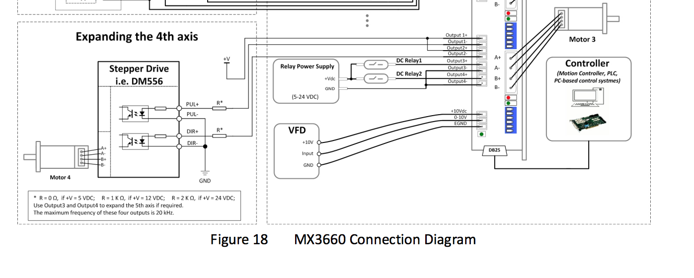
I'm adding a powered rotary table to my unit and am going to use outputs from my MX3660 (their suggested wiring diagram attached below) but it seems a bit strange to me so am looking for clarification.
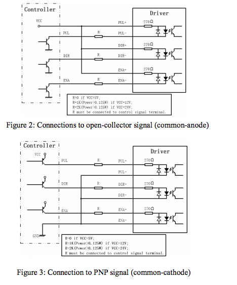
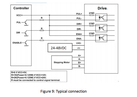
1st my power supply is 48v dc which it says my driver can take (driver is a DRIVERstepper online ) which seems to be a clone of the leadshine ( Manual here ). I've screen shotted a connection diagram and attached it too.
So my question is that the suggested wiring diagram seems strange to me. Can I just hook it direct to my PSU then wire the inputs to the out puts on my MX3660 similar to the third attachment or do I need to use resistors. If so what size resistors as my voltage is double what is described on the manual.
Cheers all in advance
Jools
Last edit: 16 Dec 2018 14:43 by jools.
Please Log in or Create an account to join the conversation.
- jools
-
 Topic Author
- Offline
- Elite Member
-

Less
More
- Posts: 161
- Thank you received: 15
16 Dec 2018 14:43 #122474
by jools
Replied by jools on topic Wiring a 4th axis
Please Log in or Create an account to join the conversation.
- pl7i92
-

- Offline
- Platinum Member
-

Less
More
- Posts: 1872
- Thank you received: 358
16 Dec 2018 15:32 #122477
by pl7i92
Replied by pl7i92 on topic Wiring a 4th axis
I personally like the Oposit more
GET the ENA + DIR+ Step + to 5V Fix
and let the controller be the GND Sinalisation
Gives you way more speed
Also more Sfafty NO steplos as pulsing is more stable
GET the ENA + DIR+ Step + to 5V Fix
and let the controller be the GND Sinalisation
Gives you way more speed
Also more Sfafty NO steplos as pulsing is more stable
Please Log in or Create an account to join the conversation.
- jools
-
 Topic Author
- Offline
- Elite Member
-

Less
More
- Posts: 161
- Thank you received: 15
17 Dec 2018 19:01 #122530
by jools
I kept with this purely as it's whats in the manual. My electronics skills are pretty average.
Replied by jools on topic Wiring a 4th axis
I personally like the Oposit more
GET the ENA + DIR+ Step + to 5V Fix
and let the controller be the GND Sinalisation
Gives you way more speed
Also more Sfafty NO steplos as pulsing is more stable
I kept with this purely as it's whats in the manual. My electronics skills are pretty average.
Please Log in or Create an account to join the conversation.
- pl7i92
-

- Offline
- Platinum Member
-

Less
More
- Posts: 1872
- Thank you received: 358
18 Dec 2018 09:42 #122561
by pl7i92
Replied by pl7i92 on topic Wiring a 4th axis
on most Break Out Boards the Outputs are Standard High
so at Drivers Set up like Yours they will all step at Power On
Therefore the system to Ground means on Power up Plus meets Plus so no Action
Up to You it works both Way
so at Drivers Set up like Yours they will all step at Power On
Therefore the system to Ground means on Power up Plus meets Plus so no Action
Up to You it works both Way
Please Log in or Create an account to join the conversation.
Time to create page: 0.239 seconds


