Kerf width programming dxf2gcode plasma using G41 G42
- Grotius
-
 Topic Author
- Offline
- Platinum Member
-

Less
More
- Posts: 2419
- Thank you received: 2348
15 Jan 2019 00:04 #124201
by Grotius
Kerf width programming dxf2gcode plasma using G41 G42 was created by Grotius
Hi,
I had to solve the kerf width programming. Normally cam program's will calculate your kerf width offset and the output in the g-code
will be a G1, G2 or G3 during cutting. So this is good. I used it year's and year's that way.
My plasma component i called it THC2.comp does everything i want. It has a travelheigt, cutheight, pierceheight, delay's the whole
circus is implemented. Even probing on a certain xy distance is included, so i am happy with this piece of software.
But kerf width compensation G41 and G42 was alway's a dark room for me. I tried it 2 times in the past to use this. But without much succes. But yesterday and today i did my best and i solved it thanks to the dxf2gcode software.
So now the kerf width offset way looks like microstep is using their machine's.
Microstep is good in plasma 2.5d operation's. They have special
cam software to do this. But i am close to a 2.5d solution now.
Question. What is exactly the difference between G41 and G41.1 ? I don't understand the documentation explanation.
linuxcnc.org/docs/html/gcode/g-code.html#gcode:g43.1
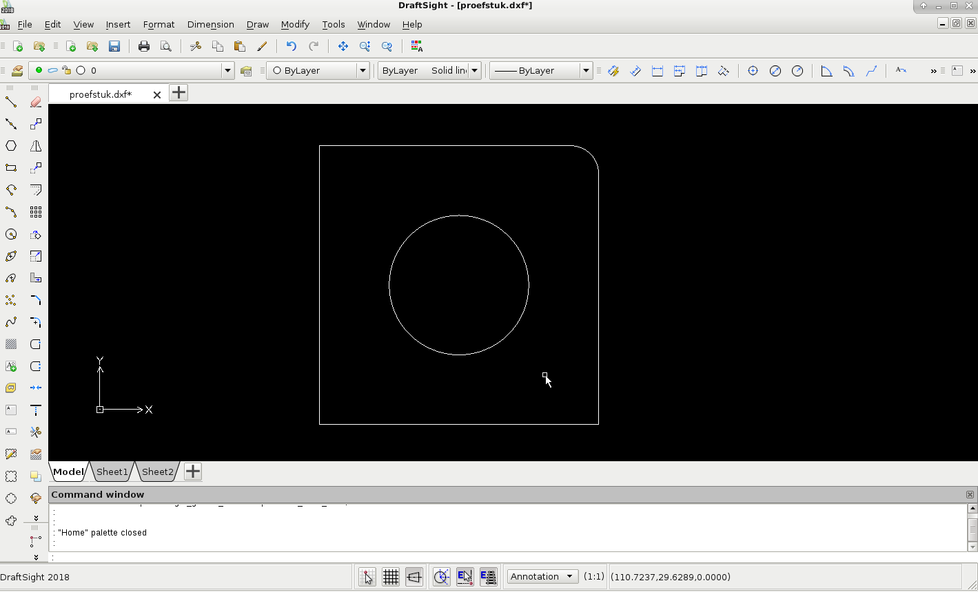
I started with drafsight 64 bit, a piece 100x100mm whole in the middle 50mm :
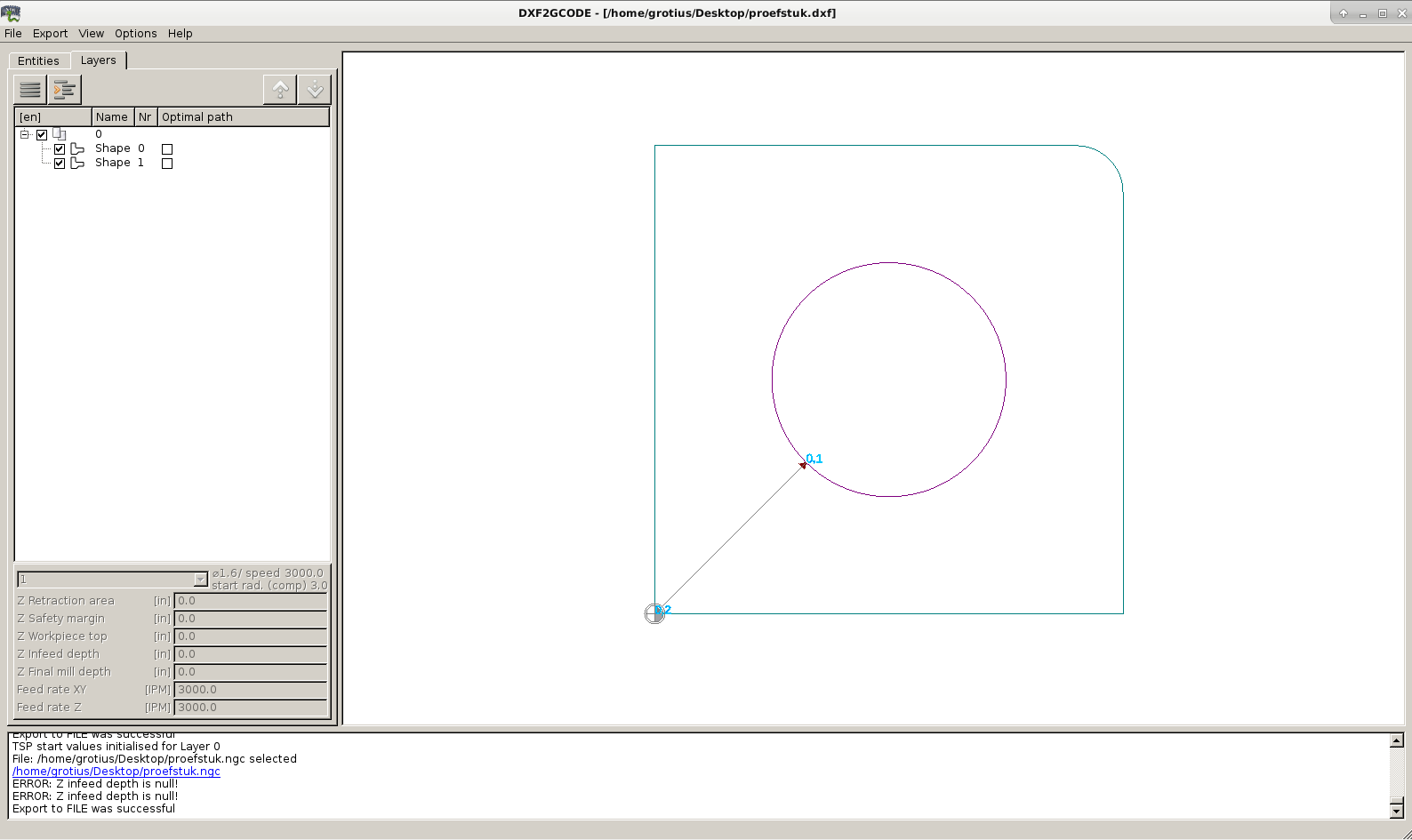
Then i played some time in dxf2gcode. I had to switch to mm and by the G64 i added P0.01
A few things and it works.
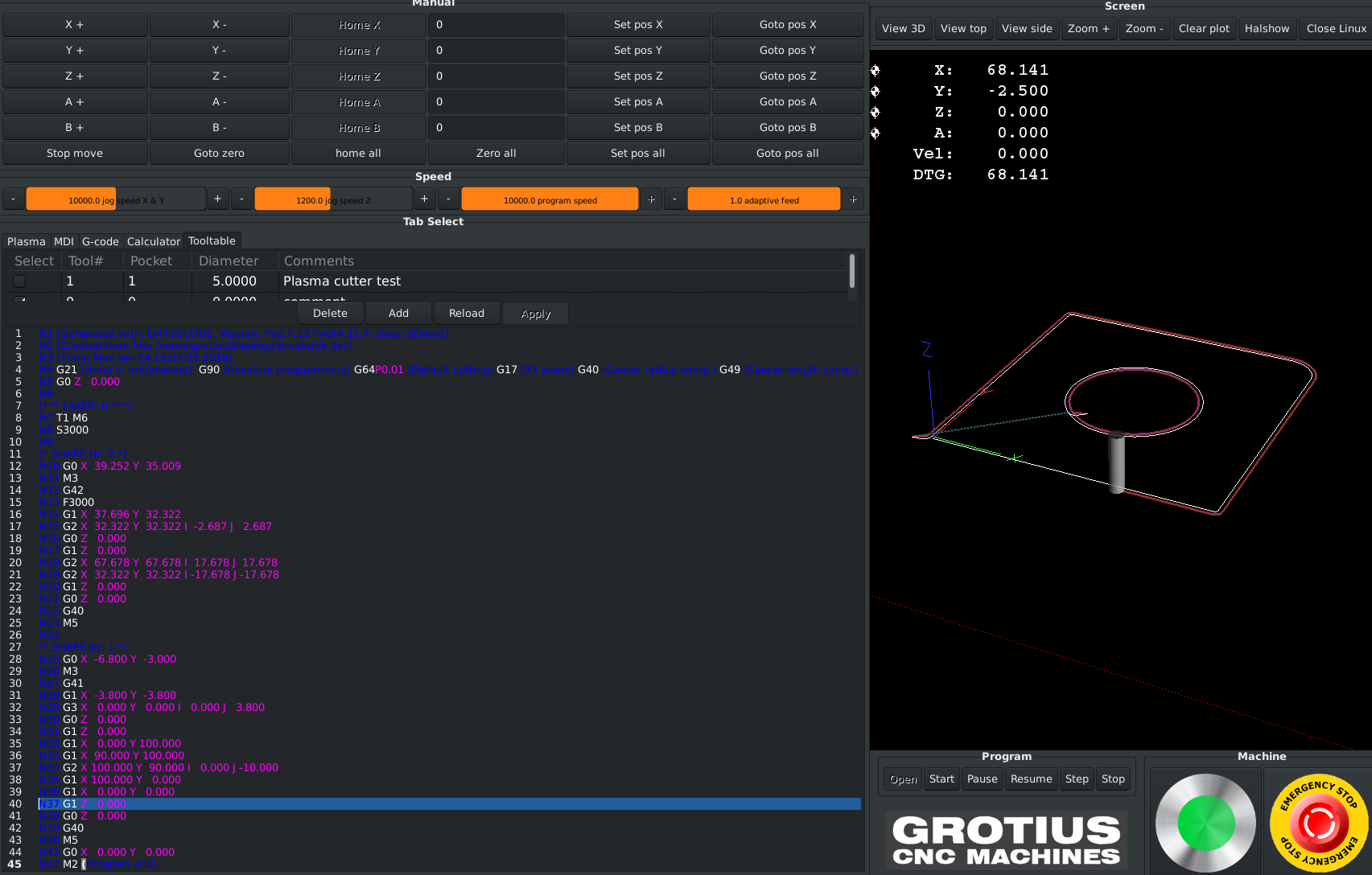
Then i added a tool list to my gui with glade. And in python code i added 2 lines :
self.widgets.tooledit1.set_filename("tool.tbl")
self.widgets.tooledit1.set_visible("abcxyzuvwijq", False)
Then i started the progam. It works... Kerf width offset with plasma is done. Wow.
Now i can expand this with the plasma tool library.
I had to solve the kerf width programming. Normally cam program's will calculate your kerf width offset and the output in the g-code
will be a G1, G2 or G3 during cutting. So this is good. I used it year's and year's that way.
My plasma component i called it THC2.comp does everything i want. It has a travelheigt, cutheight, pierceheight, delay's the whole
circus is implemented. Even probing on a certain xy distance is included, so i am happy with this piece of software.
But kerf width compensation G41 and G42 was alway's a dark room for me. I tried it 2 times in the past to use this. But without much succes. But yesterday and today i did my best and i solved it thanks to the dxf2gcode software.
So now the kerf width offset way looks like microstep is using their machine's.
Microstep is good in plasma 2.5d operation's. They have special
cam software to do this. But i am close to a 2.5d solution now.
Question. What is exactly the difference between G41 and G41.1 ? I don't understand the documentation explanation.
linuxcnc.org/docs/html/gcode/g-code.html#gcode:g43.1
I started with drafsight 64 bit, a piece 100x100mm whole in the middle 50mm :
Then i played some time in dxf2gcode. I had to switch to mm and by the G64 i added P0.01
A few things and it works.
Then i added a tool list to my gui with glade. And in python code i added 2 lines :
self.widgets.tooledit1.set_filename("tool.tbl")
self.widgets.tooledit1.set_visible("abcxyzuvwijq", False)
Then i started the progam. It works... Kerf width offset with plasma is done. Wow.
Now i can expand this with the plasma tool library.
Please Log in or Create an account to join the conversation.
- BigJohnT
-

- Offline
- Administrator
-

Less
More
- Posts: 3990
- Thank you received: 994
15 Jan 2019 00:09 #124202
by BigJohnT
Replied by BigJohnT on topic Kerf width programming dxf2gcode plasma using G41 G42
G41 D is tool number, G41.1 D is diameter.
JT
JT
The following user(s) said Thank You: Grotius
Please Log in or Create an account to join the conversation.
- Grotius
-
Topic Author
- Offline
- Platinum Member
-
Less
More
- Posts: 2419
- Thank you received: 2348
15 Jan 2019 00:19 - 15 Jan 2019 00:19 #124204
by Grotius
Replied by Grotius on topic Kerf width programming dxf2gcode plasma using G41 G42
Thanks John,
I think G41.1 is usefull for plasma.
You where one of the developpers of dxf2gcode?
If so, do you know the reason why dxf2gcode needs much time with bigger data file's?
I have soon an application that is time critical. It takes live pictures on moving belt, machine must have the gcode output
within 0.5 second. Is there a way to speed up dxf2gode output process that you now? Is there any source code that can be deleted to fasten
up the process you know or think about?
I forgot to post the gui result.
Attachments:
Last edit: 15 Jan 2019 00:19 by Grotius.
Please Log in or Create an account to join the conversation.
- BigJohnT
-
- Offline
- Administrator
-
Less
More
- Posts: 3990
- Thank you received: 994
15 Jan 2019 15:47 #124234
by BigJohnT
Replied by BigJohnT on topic Kerf width programming dxf2gcode plasma using G41 G42
I did develop a G code generator but probably not the one your using as mine is super fast and unfinished.
Mine is DXFtoGcode github.com/jethornton/DXFtoGcode
JT
Mine is DXFtoGcode github.com/jethornton/DXFtoGcode
JT
The following user(s) said Thank You: Grotius
Please Log in or Create an account to join the conversation.
- Grotius
-
Topic Author
- Offline
- Platinum Member
-
Less
More
- Posts: 2419
- Thank you received: 2348
18 Jan 2019 22:15 - 18 Jan 2019 22:36 #124418
by Grotius
Replied by Grotius on topic Kerf width programming dxf2gcode plasma using G41 G42
Hi John,
I have looked at your gcode generator. I am impressed by the simplicity.
You are a good coder John.
For me is new the google programming language.
I thought i start it up with terminal command : python dxf.py
But it seems to be complicater then that. Until now i did not make succes to convert a drawing.
I got some error output. Coming day's i maybe find out what the problem is. I did not install the go.
In fact the appllication is starting up and file is loading. But converting output's a terminal problem.
The glade file i can not open. Maybe related to a glade version, but less important for me. I can solve that.
But if it work's it can be a nice template to build on and add some function's like lead in and lead out to start with.
And very important. It's super fast !
Do you think it is possible to convert the files that has a google language into c language? If yes, maybe i can give it a go.
Related to the G41 and G42 i see a linuxcnc problem.
When i cut a plate of 2000x1000mm with kerf (tooldiameter) 1.6mm. I don't see my tool anymore. It's so tiny displayed at that moment. So we have to solve this in the source code. I think the tooling has not to be scaled with the workpiece. I like it when i can see where my tool is. In the past i was searching for the standard cone feature's in gremlin (g0,1,2,3 action's). So i have to do some research about this in coming time.
Last edit: 18 Jan 2019 22:36 by Grotius.
Please Log in or Create an account to join the conversation.
Time to create page: 0.120 seconds