PUMA geometry
- felixcnc
-
 Topic Author
- Offline
- Junior Member
-

Less
More
- Posts: 29
- Thank you received: 0
14 Jun 2019 21:37 #136917
by felixcnc
arm size was created by felixcnc
Hello there,
I keep reading and investigating but there's something still unclear to me. Basically is how to set the arm sizes?.
I am always using a PUMA as an example because it's the kind of robot we would like to investigate at the university (a six degrees of freedom robot), and I understood like 80% of the configurations there but I still don't understand how the arm sections are configured.
The pumakins calculate the position of the head, but definitely there should be a way to configure the arm sizes, so basically:
So for example this robot:
and this robot
are essentially the same robot, but they differ in sizes, therefore when I move or execute G code the resulting position of the tip of the tool will be in a different point in space. So I am guessing that I should configure the robot size somewhere, but I couldn't find it.
Where is the configuration for the arm size? (for example in a PUMA robot)
Thank you very much!
Kind regards
I keep reading and investigating but there's something still unclear to me. Basically is how to set the arm sizes?.
I am always using a PUMA as an example because it's the kind of robot we would like to investigate at the university (a six degrees of freedom robot), and I understood like 80% of the configurations there but I still don't understand how the arm sections are configured.
The pumakins calculate the position of the head, but definitely there should be a way to configure the arm sizes, so basically:
So for example this robot:
    ___
   /   |
  |    V
  |
-----
and this robot
     ___
    /   |
   /    |
  |     V
  |
  |
  |
  |
-----
are essentially the same robot, but they differ in sizes, therefore when I move or execute G code the resulting position of the tip of the tool will be in a different point in space. So I am guessing that I should configure the robot size somewhere, but I couldn't find it.
Where is the configuration for the arm size? (for example in a PUMA robot)
Thank you very much!
Kind regards
Please Log in or Create an account to join the conversation.
- pl7i92
-

- Offline
- Platinum Member
-

Less
More
- Posts: 1872
- Thank you received: 358
15 Jun 2019 08:10 - 15 Jun 2019 08:43 #136963
by pl7i92
Replied by pl7i92 on topic arm size
this is the part of the POSTPROCESSOR of your CAM
it gives only the Degreeses of the Joints to the Robot
as this is the Factor to run it
but you are right there are entries in pumaskin.h
I think in your case it is all fairly easy.
Joint 0 has zero for all parameters.
Joint 1 has alpha = pi/2 d = offset, alpha = 0, r = 0
joint 2 has alpha = 0, theta = 0 , d=0, r = upper-arm length,
joint 3 has alpha = 0, theta = 0. d = 0, r = forearm arm length
joint 4 has alpha =0, theta = pi/2 d= wrist joint offset r = 0
as you use pumakins
The pumakins kinematics module creates 4 "pins" in the HAL that can be set to suit the geometry of your robot.
You would use lines like:
setp pumakins.A2 200
setp pumakins.A3 300
setp pumakins.D3 100
setp pumakins.D4 500
to set the kinematics to suit your particular robot.
The A and D values are the Denavit-Hartenberg parameters of your robot.
en.wikipedia.org/wiki/Denavit-Hartenberg_Parameters
Last edit: 15 Jun 2019 08:43 by pl7i92. Reason: kins parameter
Please Log in or Create an account to join the conversation.
- felixcnc
-
Topic Author
- Offline
- Junior Member
-
Less
More
- Posts: 29
- Thank you received: 0
16 Jun 2019 00:40 #137016
by felixcnc
Replied by felixcnc on topic arm size
This is an eye opening comment. Thanks.
So according to what you have said, the values set in the puma_sim_6.hal means this:
setp pumakins.A2 200 => Joint1 d=200
setp pumakins.A3 300 => Joint2 d=300
setp pumakins.D3 100 => Joint3 d=100
setp pumakins.D4 500 => Joint4 d=500
Is this correct?
Thank you very much!
Pd: It seems the following thread is related
forum.linuxcnc.org/10-advanced-configura...e-kinematics?start=0
Please Log in or Create an account to join the conversation.
- andypugh
-

- Offline
- Moderator
-

Less
More
- Posts: 19875
- Thank you received: 4642
18 Jun 2019 22:32 #137238
by andypugh
Replied by andypugh on topic arm size
You can't use => with a setp command.
But it isn't clear if that is what you were suggesting.
But it isn't clear if that is what you were suggesting.
Please Log in or Create an account to join the conversation.
- felixcnc
-
Topic Author
- Offline
- Junior Member
-
Less
More
- Posts: 29
- Thank you received: 0
19 Jun 2019 00:39 #137255
by felixcnc
Replied by felixcnc on topic arm size
Sorry, that was not what I meant. It was an "abuse of notation"; it was more like a mathematical IMPLICATION therefore:
setp pumakins.A2 200 => Joint1 d=200
meant
setp pumakins.A2 200 IMPLIES Joint1 d=200
and so on.
Thanks for pointing that out!
Kind regards.
setp pumakins.A2 200 => Joint1 d=200
meant
setp pumakins.A2 200 IMPLIES Joint1 d=200
and so on.
Thanks for pointing that out!
Kind regards.
Please Log in or Create an account to join the conversation.
- felixcnc
-
Topic Author
- Offline
- Junior Member
-
Less
More
- Posts: 29
- Thank you received: 0
19 Jun 2019 02:40 #137264
by felixcnc
Replied by felixcnc on topic PUMA geometry
I was reading the parameters in the Denavit-Hartenberg matrix but I wasn't able to map that into the PUMA definition, because PUMA has 6 joints, not 5.
So HAL shows this:
So for example according to the D-H matrix there are 4 parameters per joint:
So I guess the geometry is already defined in the file pumakins.c (which is still beyond my understanding), so I guess the values that are in the HAL are just the SIZES of each arm (or the offsets), however the values don't make sense to me.
Please, Can someone help me to understand the PUMA geometry? (for example I would like to use an emulator to send signals from LinuxCNC to a virtual PUMA, but I need all the Denavit-Hartemberg parameters and I don't know how to extract them.
Also Can someone explain to me what are the following values defined in the HAL for the PUMA?
Thanks again for all your help. I feel silly , but I spent a few hours reading wikipedia , the C code and couldn't find any help, and every time I ask here you gave me lots of good answers.
Thank you very much
Kind regards.
So HAL shows this:
setp pumakins.A2 400
setp pumakins.A3 50
setp pumakins.D3 100
setp pumakins.D4 400
setp pumakins.D6 95
So for example according to the D-H matrix there are 4 parameters per joint:
- theta : The angle the joint is rotated
- alpha : The twist angle for the link
- d : Offset
- a : Link length
So I guess the geometry is already defined in the file pumakins.c (which is still beyond my understanding), so I guess the values that are in the HAL are just the SIZES of each arm (or the offsets), however the values don't make sense to me.
Please, Can someone help me to understand the PUMA geometry? (for example I would like to use an emulator to send signals from LinuxCNC to a virtual PUMA, but I need all the Denavit-Hartemberg parameters and I don't know how to extract them.
Also Can someone explain to me what are the following values defined in the HAL for the PUMA?
setp pumakins.A2 400
setp pumakins.A3 50
setp pumakins.D3 100
setp pumakins.D4 400
setp pumakins.D6 95
Thanks again for all your help. I feel silly , but I spent a few hours reading wikipedia , the C code and couldn't find any help, and every time I ask here you gave me lots of good answers.
Thank you very much
Kind regards.
Please Log in or Create an account to join the conversation.
- andypugh
-
- Offline
- Moderator
-
Less
More
- Posts: 19875
- Thank you received: 4642
19 Jun 2019 08:56 #137274
by andypugh
I think it only has 4 joints?
Waist rotation, shoulder rotation, elbow rotation and wrist rotation.
The wrist is assumed to be in-line with the forearm and all joints are at 90 degree angles, and so you only really need to define 3 arm lengths and 2 offsets
Try the config sim->axis->vismach->puma->puma560 for a Puma simulator (with onscreen virtual robot)
Replied by andypugh on topic PUMA geometry
I was reading the parameters in the Denavit-Hartenberg matrix but I wasn't able to map that into the PUMA definition, because PUMA has 6 joints, not 5
I think it only has 4 joints?
Waist rotation, shoulder rotation, elbow rotation and wrist rotation.
The wrist is assumed to be in-line with the forearm and all joints are at 90 degree angles, and so you only really need to define 3 arm lengths and 2 offsets
Please, Can someone help me to understand the PUMA geometry? (for example I would like to use an emulator to send signals from LinuxCNC to a virtual PUMA,.
Try the config sim->axis->vismach->puma->puma560 for a Puma simulator (with onscreen virtual robot)
Please Log in or Create an account to join the conversation.
- felixcnc
-
Topic Author
- Offline
- Junior Member
-
Less
More
- Posts: 29
- Thank you received: 0
19 Jun 2019 09:45 #137275
by felixcnc
Replied by felixcnc on topic PUMA geometry
Hi Andypugh,
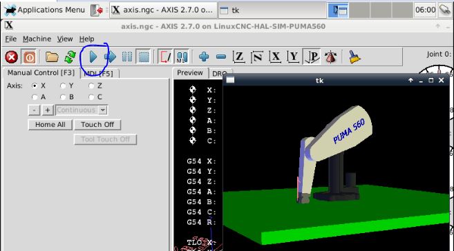
Thanks for your answer, but mine looks quite different. Attached you'll find how it looks for me, and any version of the puma for me looks to have 6 joints:
Perhaps I am wrong, but that's what I see when I move the joints separately.
Thanks
Kind regards
Thanks for your answer, but mine looks quite different. Attached you'll find how it looks for me, and any version of the puma for me looks to have 6 joints:
- 3 joints for the body: 1 attached to the table, 1 attached to the end of the first link, and 1 attached to the end of the second link
- 3 joints for the "hand": 1 attached to the wrist (rotation), 1 attached to the wrist (up-down), 1 rotation to the tool
Perhaps I am wrong, but that's what I see when I move the joints separately.
Thanks
Kind regards
Please Log in or Create an account to join the conversation.
- andypugh
-
- Offline
- Moderator
-
Less
More
- Posts: 19875
- Thank you received: 4642
19 Jun 2019 10:06 #137276
by andypugh
Replied by andypugh on topic PUMA geometry
The Vismach Puma folder contains three separate configs "puma", "puma_cube" and "puma560". These have different Vismach models.
puma and puma_cube use pumakins, puma560 uses genserkins
linuxcnc.org/docs/2.8/html/man/man9/genserkins.9.html
Neither kins is particularly well documented
linuxcnc.org/docs/2.8/html/man/man9/genserkins.9.html
I know that genserkins uses "modified" DH paramters, I am not sure which Pumakins uses.
One thing I recently found helpful was:
forum.linuxcnc.org/10-advanced-configura...rg-parameters#134884
Please Log in or Create an account to join the conversation.
Time to create page: 0.292 seconds