Odd velocity mode servo tuning issues
- Juckix
- Offline
- Junior Member
-

Less
More
- Posts: 31
- Thank you received: 0
11 Jul 2019 14:52 #139108
by Juckix
Odd velocity mode servo tuning issues was created by Juckix
Once again I'm having issues with servo tuning on a retrofit. This time it's about actual move performance of the X axis.
The system is an analog velocity mode servo on a leadscrew run through a Mesa 7i92+7i77 combo. The problem is as follows. No matter how I try to tune this axis there is (worryingly) audible oscillation during moves, even with the most modest of tunes (P:1, I:0, D:0 for example), but it gets really pronounced at more aggressive tunes. As for troubleshooting I know this:
- Encoder is functioning correctly. It produces accurate DRO numbers both in open and closed loop movement.
- Motor and drive combination are stable, open loop tests produce similar stability during movement as the successfully tuned Y axis.
At this point I'm not sure where to continue troubleshooting, so any ideas are appreciated.
Please Log in or Create an account to join the conversation.
- PCW
-

- Online
- Moderator
-

Less
More
- Posts: 17995
- Thank you received: 5281
11 Jul 2019 15:40 #139110
by PCW
Replied by PCW on topic Odd velocity mode servo tuning issues
Velocity mode tuning is 99% FF1
Do you get oscillations when FF1 is correct and just a small amount of P?
If so, this is a drive tuning issue, not something that can be fixed in LinuxCNC
A halscope plot of the following error would help with diagnosis
Do you get oscillations when FF1 is correct and just a small amount of P?
If so, this is a drive tuning issue, not something that can be fixed in LinuxCNC
A halscope plot of the following error would help with diagnosis
Please Log in or Create an account to join the conversation.
- Juckix
- Offline
- Junior Member
-
Less
More
- Posts: 31
- Thank you received: 0
11 Jul 2019 16:25 #139115
by Juckix
I'll get you the plot. I have tried a P, FF1, FF2 tuning tutorial (gnipsel.com/linuxcnc/tuning/servo.html) as well as done some experimenting of my own and I can't seem to get any good results. The parameters used right now are actually P:13 FF1:0.113 FF2:0.00072 but oscillations still occur.
But as mentioned the drive and motor function perfectly fine in open loop, how could the issue be with those? And the Y stage has no such problem with a PID tune, in fact adding FF1 there seemed to not have much of any effect on the error plots.
Replied by Juckix on topic Odd velocity mode servo tuning issues
Velocity mode tuning is 99% FF1
Do you get oscillations when FF1 is correct and just a small amount of P?
If so, this is a drive tuning issue, not something that can be fixed in LinuxCNC
A halscope plot of the following error would help with diagnosis
I'll get you the plot. I have tried a P, FF1, FF2 tuning tutorial (gnipsel.com/linuxcnc/tuning/servo.html) as well as done some experimenting of my own and I can't seem to get any good results. The parameters used right now are actually P:13 FF1:0.113 FF2:0.00072 but oscillations still occur.
But as mentioned the drive and motor function perfectly fine in open loop, how could the issue be with those? And the Y stage has no such problem with a PID tune, in fact adding FF1 there seemed to not have much of any effect on the error plots.
Please Log in or Create an account to join the conversation.
- PCW
-
- Online
- Moderator
-
Less
More
- Posts: 17995
- Thank you received: 5281
11 Jul 2019 16:55 - 11 Jul 2019 16:56 #139117
by PCW
Replied by PCW on topic Odd velocity mode servo tuning issues
if adding FF1 made little difference, something is very wrong...
FF1 is the most important tuning factor for velocity mode drives
Is it possible that the drives are not running in velocity mode?
How do the drives get velocity feedback?
One easy way to check if the drives are running properly in velocity mode is
to command a very slow speed open loop ( P=0 ) and make sure the motor rotates
smoothly with full torque even at 1 RPM or less
Last edit: 11 Jul 2019 16:56 by PCW.
Please Log in or Create an account to join the conversation.
- Juckix
- Offline
- Junior Member
-
Less
More
- Posts: 31
- Thank you received: 0
11 Jul 2019 17:04 #139118
by Juckix
The drives get velocity feedback via tachometers mounted on the axle of the servos, very similar to the spindle system installed. They are certainly velocity mode as an open loop test gives a velocity plot that is flat (within reason) for a given voltage.
I can do a P=0 test when I have the opportunity.
Replied by Juckix on topic Odd velocity mode servo tuning issues
if adding FF1 made little difference, something is very wrong...
FF1 is the most important tuning factor for velocity mode drives
Is it possible that the drives are not running in velocity mode?
How do the drives get velocity feedback?
One easy way to check if the drives are running properly in velocity mode is
to command a very slow speed open loop ( P=0 ) and make sure the motor rotates
smoothly with full torque even at 1 RPM or less
The drives get velocity feedback via tachometers mounted on the axle of the servos, very similar to the spindle system installed. They are certainly velocity mode as an open loop test gives a velocity plot that is flat (within reason) for a given voltage.
I can do a P=0 test when I have the opportunity.
Please Log in or Create an account to join the conversation.
- Juckix
- Offline
- Junior Member
-
Less
More
- Posts: 31
- Thank you received: 0
16 Jul 2019 14:03 #139560
by Juckix
Replied by Juckix on topic Odd velocity mode servo tuning issues
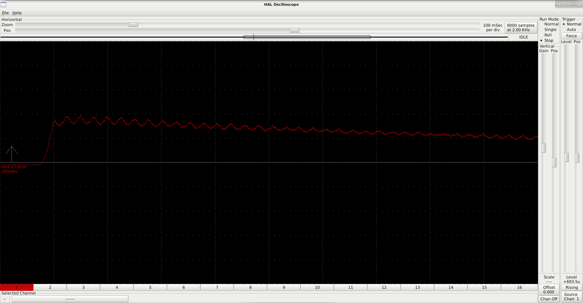
Here are some follow error graphs as well as current tuning parameters for X (which is difficult to tune) and Y (which seems to be performing satisfactorily). Axis 0 is X, axis 1 is Y.
Setting P=0 and commanding a continuous jog produces no movement, and leads to a joint following error eventually, which is what I expected. However, open loop testing in pncconf shows stable movement at low velocities.
X follow error and tune parameters. No oscillation is visible but note the significant constant follow error even during jog, this along with audible noise is the problem.


Y follow error and tune parameters. Oscillation is visible in the graph but system corrects error. Maybe not the best tune. Of course if FF1 ends up helping, this would be good to improve too.

Setting P=0 and commanding a continuous jog produces no movement, and leads to a joint following error eventually, which is what I expected. However, open loop testing in pncconf shows stable movement at low velocities.
X follow error and tune parameters. No oscillation is visible but note the significant constant follow error even during jog, this along with audible noise is the problem.
Y follow error and tune parameters. Oscillation is visible in the graph but system corrects error. Maybe not the best tune. Of course if FF1 ends up helping, this would be good to improve too.
Attachments:
Please Log in or Create an account to join the conversation.
- PCW
-
- Online
- Moderator
-
Less
More
- Posts: 17995
- Thank you received: 5281
16 Jul 2019 14:14 - 16 Jul 2019 14:19 #139561
by PCW
Replied by PCW on topic Odd velocity mode servo tuning issues
If the drives and interface were perfect velocity mode devices, all you would need would be FF1...
For velocity mode drives, FF1 _must_ be right or there is no hope of decent tuning.
Otherwise you will be trying to fix the following error with excessive P term, leading to oscillations
Plotting the commanded velocity would help with interpretation, as would normalizing the
analog output so its in units of velocity, if this is done, FF1==1.0
Normalizing makes all the PID parameters scaled in direct engineering units
The way you do this is by setting the analog output scale (and limits)
to machine units per second at 10V
Last edit: 16 Jul 2019 14:19 by PCW.
Please Log in or Create an account to join the conversation.
- Juckix
- Offline
- Junior Member
-
Less
More
- Posts: 31
- Thank you received: 0
16 Jul 2019 14:34 - 16 Jul 2019 14:34 #139562
by Juckix
I'll see if I can get those graphs. I feel like I don't understand the PID component and the Linuxcnc motion controller well enough yet.
Would you mind sanity checking my PID setup so that it's correct? I'm thinking that it seems like it uses a position error to set a velocity output which doesn't seem right, but maybe I'm misunderstanding something.
Replied by Juckix on topic Odd velocity mode servo tuning issues
If the drives and interface were perfect velocity mode devices, all you would need would be FF1...
For velocity mode drives, FF1 _must_ be right or there is no hope of decent tuning.
Otherwise you will be trying to fix the following error with excessive P term, leading to oscillations
Plotting the commanded velocity would help with interpretation, as would normalizing the
analog output so its in units of velocity, if this is done, FF1==1.0
Normalizing makes all the PID parameters scaled in direct engineering units
The way you do this is by setting the analog output scale (and limits)
to machine units per second at 10V
I'll see if I can get those graphs. I feel like I don't understand the PID component and the Linuxcnc motion controller well enough yet.
Would you mind sanity checking my PID setup so that it's correct? I'm thinking that it seems like it uses a position error to set a velocity output which doesn't seem right, but maybe I'm misunderstanding something.
#*******************
#  AXIS X
#*******************

setp   pid.x.Pgain     [AXIS_0]P
setp   pid.x.Igain     [AXIS_0]I
setp   pid.x.Dgain     [AXIS_0]D
setp   pid.x.bias      [AXIS_0]BIAS
setp   pid.x.FF0       [AXIS_0]FF0
setp   pid.x.FF1       [AXIS_0]FF1
setp   pid.x.FF2       [AXIS_0]FF2
setp   pid.x.deadband  [AXIS_0]DEADBAND
setp   pid.x.maxoutput [AXIS_0]MAX_OUTPUT
setp   pid.x.error-previous-target true

net x-index-enable  <=> pid.x.index-enable
net x-enable        =>  pid.x.enable
net x-pos-cmd       =>  pid.x.command
net x-vel-cmd       =>  pid.x.command-deriv
net x-pos-fb        =>  pid.x.feedback
net x-output        =>  pid.x.output

# ---PWM Generator signals/setup---

setp   hm2_7i92.0.7i77.0.1.analogout0-scalemax  [AXIS_0]OUTPUT_SCALE
setp   hm2_7i92.0.7i77.0.1.analogout0-minlim    [AXIS_0]OUTPUT_MIN_LIMIT
setp   hm2_7i92.0.7i77.0.1.analogout0-maxlim    [AXIS_0]OUTPUT_MAX_LIMIT

net x-output => hm2_7i92.0.7i77.0.1.analogout0
net x-pos-cmd axis.0.motor-pos-cmd
net x-enable axis.0.amp-enable-out
# enable _all_ sserial pwmgens
net x-enable hm2_7i92.0.7i77.0.1.analogena
Last edit: 16 Jul 2019 14:34 by Juckix.
Please Log in or Create an account to join the conversation.
- PCW
-
- Online
- Moderator
-
Less
More
- Posts: 17995
- Thank you received: 5281
16 Jul 2019 15:05 #139563
by PCW
Replied by PCW on topic Odd velocity mode servo tuning issues
Yes, that's correct, for a velocity mode drive, with a position mode PID loop,
the position error *P = velocity _correction_
Note the _correction_, FF1 should have the axis moving at the correct velocity before any corrections are applied. One way to look at this is that the P term is only used to correct for imperfections in the drives velocity following, minor timing errors, interface/drive offsets and resolution limitations.
You might try commenting out this line:
net x-vel-cmd => pid.x.command-deriv
In case its not connected properly on the rest of the hal file
(if that line is commented out the PID component will calculate velocity/FF1 from DP/DT)
Please Log in or Create an account to join the conversation.
- Juckix
- Offline
- Junior Member
-
Less
More
- Posts: 31
- Thank you received: 0
16 Jul 2019 15:08 #139564
by Juckix
I'll try that, and thanks for the explanation.
Replied by Juckix on topic Odd velocity mode servo tuning issues
Yes, that's correct, for a velocity mode drive, with a position mode PID loop,
the position error *P = velocity _correction_
Note the _correction_, FF1 should have the axis moving at the correct velocity before any corrections are applied. One way to look at this is that the P term is only used to correct for imperfections in the drives velocity following, minor timing errors, interface/drive offsets and resolution limitations.
You might try commenting out this line:
net x-vel-cmd => pid.x.command-deriv
In case its not connected properly on the rest of the hal file
(if that line is commented out the PID component will calculate velocity/FF1 from DP/DT)
I'll try that, and thanks for the explanation.
Please Log in or Create an account to join the conversation.
Time to create page: 0.195 seconds