Custom Kinematics
- Todd Zuercher
-
 Topic Author
- Away
- Platinum Member
-

Less
More
- Posts: 4764
- Thank you received: 1464
17 Oct 2019 15:04 #148123
by Todd Zuercher
Custom Kinematics was created by Todd Zuercher
I have an idea for a machine I'm considering a retrofit for.
The machine in question is a 4 spindle router. used for carving and engraving 4 items at a time. Each spindle is mounted to an independent Z-axis, labled Z,U,V,W in the current control. The machine is used almost exclusively for carving 4x of the same thing. And the g-code is set up with only XYZ commands but uses a special g-code to temporarily slave all 4 vertical axis together so they follow the same Z command. The temporary slaving command works like this you command all of the axis you wish to slave together to a common position in the coordinate system you are using (such as your safe retract height above the material. then issue the slaving commad, then all the slaved axis follow the master one's commands until released. This machine also is a gantry with a slaved joint for the Y axis, this I will want to keep the current gantry features currently used in 2.8+.
I have setup similar machines in Linuxcnc with 2 Z-axis (ZW) and set up temporary slaving with some complicated hal kludgery and it works OK. But If I do this bigger machine I want to setup something better. I was thinking the ideal place to do this would be in a custom kinematics file. But I have not been able to pull together the programming skills to do it.
I think I have some good ideas how to make the Kinematics work but I need some help putting the pieces together. In other words I have no idea how to program them.
My Ideas so far are to have three hal pins that control the slaving, one bool that activates/deactivates the temporary slaving and two S32s the that their values are used to set which of the axis and joints are to be slaved. One S32 will set which of the axis will be the master axis, and the other S32 sets which joints(or axis) will be slaved to the master one.
Will it be possible for this to have the DROs for the slaved axis continue to show the true positions without causing following error or will they have to be stuck at the point where they were slaved? Will I get a following error when unslaving if all of the axis are not returned to the same position relative to each other as when they were slaved?
In the past there had been a thread on the forum that had given an example of a custom Kinematics file (Swapkins) that would have been a start in the direction I want to go, but it falls very short of my ultimate goal, and I could not quite wrap my head around how to add what would be needed to make it do what I wanted it to. Then add in the much more complicated version of Trivkins that came with 2.8 and I find that I am way out of my depth.
Please Log in or Create an account to join the conversation.
- dgarrett
- Offline
- Platinum Member
-
Less
More
- Posts: 492
- Thank you received: 297
17 Oct 2019 21:53 - 17 Oct 2019 21:54 #148153
by dgarrett
Replied by dgarrett on topic Custom Kinematics
With existing trivkins in 2.8~pre* (and master) you can
assign specific joints to U,V,W and use a [FILTER] to
modify gcode so that the U,V,W coordinate values
are identical to the Z values.
This method uses existing features instead of custom
kinematics. I don't think custom kinematics is very
helpful since the tool heights are likely to need
touch-off for both the Z and U,V,W coordinates to
accomodate varying tool lengths. Touch-off is a
coordinate (axis letter) function not a joint
(pre-homing) function.
The attached sim config illustrates an ini file
and supplies a simple filter script (zreplicate.tcl).
The inifile uses:
This corresponds to:
JOINT_0 ==> X coordinate
JOINT_1 ==> Y0 gantry synced joint
JOINT_2 ==> Z coordinate
JOINT_3 ==> Y1 gantry synced joint
JOINT_4 ==> U coordinate
JOINT_5 ==> V coordinate
JOINT_6 ==> W coordinate
The zreplicate.tcl script filters input files according
to the file extension:
To test the sim config (no hardware required):
1) $ tar xf xyzyuvw.tar
2) $ cd xyzyuvw
3) if rip, source scripts/rip-enviroment
4) $ linuxcnc xyzyuvw.ini
5) F1,F2,Ctrl-HOME,R
6) note gcode for OPEN_FILE=test.uvw
7) Select other examples using menu File/Open/
test.u
test.uv
Notes:
1) The simple zreplicate script is based on operation
in the default G17 (XY) plane (like a mill or router).
Its parsing does not support bracketed expressions ([])
or block structures (o<>), etc. Additional scripting
would be required to parse such items.
2) With this type of configuration, one would treat the
Z (Joint_2) spindle as the master for touchoff of the
tool and the coordinate system. After touching off the
Z coordinate, the related coordinates (U,V,W) would
need to be touched off individually to accomodate each
tool height.
3) The ordering for coordinates=xyzyuvw is chosen to
align most closely with the use of the keyboard jogging
keys provided by the axis gui for joint (pre-homing)
and coordinate (post-homing) jogging.
assign specific joints to U,V,W and use a [FILTER] to
modify gcode so that the U,V,W coordinate values
are identical to the Z values.
This method uses existing features instead of custom
kinematics. I don't think custom kinematics is very
helpful since the tool heights are likely to need
touch-off for both the Z and U,V,W coordinates to
accomodate varying tool lengths. Touch-off is a
coordinate (axis letter) function not a joint
(pre-homing) function.
The attached sim config illustrates an ini file
and supplies a simple filter script (zreplicate.tcl).
The inifile uses:
[KINS]
KINEMATICS=trivkins coordinates=xyzyuvw kinstype=both
JOINTS=7
This corresponds to:
JOINT_0 ==> X coordinate
JOINT_1 ==> Y0 gantry synced joint
JOINT_2 ==> Z coordinate
JOINT_3 ==> Y1 gantry synced joint
JOINT_4 ==> U coordinate
JOINT_5 ==> V coordinate
JOINT_6 ==> W coordinate
The zreplicate.tcl script filters input files according
to the file extension:
  .u   replicate Z values on U coordinate
  .v   replicate Z values on V coordinate
  .w   replicate Z values on W coordinate
  .uv  replicate Z values on U and V coordinates
  .uw  replicate Z values on U and W coordinates
  .vw  replicate Z values on V and W coordinates
  .uvw replicate Z values on U, V and W coordinates
To test the sim config (no hardware required):
1) $ tar xf xyzyuvw.tar
2) $ cd xyzyuvw
3) if rip, source scripts/rip-enviroment
4) $ linuxcnc xyzyuvw.ini
5) F1,F2,Ctrl-HOME,R
6) note gcode for OPEN_FILE=test.uvw
7) Select other examples using menu File/Open/
test.u
test.uv
Notes:
1) The simple zreplicate script is based on operation
in the default G17 (XY) plane (like a mill or router).
Its parsing does not support bracketed expressions ([])
or block structures (o<>), etc. Additional scripting
would be required to parse such items.
2) With this type of configuration, one would treat the
Z (Joint_2) spindle as the master for touchoff of the
tool and the coordinate system. After touching off the
Z coordinate, the related coordinates (U,V,W) would
need to be touched off individually to accomodate each
tool height.
3) The ordering for coordinates=xyzyuvw is chosen to
align most closely with the use of the keyboard jogging
keys provided by the axis gui for joint (pre-homing)
and coordinate (post-homing) jogging.
Last edit: 17 Oct 2019 21:54 by dgarrett.
The following user(s) said Thank You: tommylight
Please Log in or Create an account to join the conversation.
- dgarrett
- Offline
- Platinum Member
-
Less
More
- Posts: 492
- Thank you received: 297
18 Oct 2019 03:11 #148159
by dgarrett
Replied by dgarrett on topic Custom Kinematics
After some more thought, I've updated the sim config:
1) A single master gcode file for demonstration is
test.ngc. This file uses X,Y,Z only.
2) Symbolic links are made to test.ngc to identify
which of the Z,U,V,W coordinates will be used
when the linked file is selected based on the
link file extension:
This means you can use any combination of 1,2,3 or 4
spindles. No coordinate is specifically "master";
each coordinate in use should be touched-off to set
tool height reference, unused coordinates should be
moved (up) to a safe position before running.
Notes:
1) The sim config supplies all (14) symbolic links
but in practice only the ones to be used are needed.
2) If a linked file does not specify the z coordinate
(like test.uv or test.uvw), the axis gui does not show
the path z component since it only knows how to
display X,Y,Z. (The DRO is correct for all Z,U,V,W
coordinates in use).
Attached xyzyuvw_v2.tar
1) A single master gcode file for demonstration is
test.ngc. This file uses X,Y,Z only.
2) Symbolic links are made to test.ngc to identify
which of the Z,U,V,W coordinates will be used
when the linked file is selected based on the
link file extension:
  test.z ----- Z
  test.u ----- U
  test.v ----- V
  test.w ----- W
  test.zu ---- Z,U
  test.zv ---- Z,V
  ...
  test.uvw --- U,V,W
  test.zuvw -- Z,U,V,W
This means you can use any combination of 1,2,3 or 4
spindles. No coordinate is specifically "master";
each coordinate in use should be touched-off to set
tool height reference, unused coordinates should be
moved (up) to a safe position before running.
Notes:
1) The sim config supplies all (14) symbolic links
but in practice only the ones to be used are needed.
2) If a linked file does not specify the z coordinate
(like test.uv or test.uvw), the axis gui does not show
the path z component since it only knows how to
display X,Y,Z. (The DRO is correct for all Z,U,V,W
coordinates in use).
Attached xyzyuvw_v2.tar
The following user(s) said Thank You: tommylight
Please Log in or Create an account to join the conversation.
- Todd Zuercher
-
Topic Author
- Away
- Platinum Member
-
Less
More
- Posts: 4764
- Thank you received: 1464
18 Oct 2019 03:34 #148160
by Todd Zuercher
Replied by Todd Zuercher on topic Custom Kinematics
Thanks, but I have used similar filter scripts on my xyzw machines before. I switched to the temporary slaving when I found that the new tool planner did not support multi-line look ahead with axis other than xyz.
I know it can work, I just need a way to execute it.
The kins when commanded to slave, will need to calculate an offset(s) of the difference between the master axis and each slave at the point where the slaving command is given. Then simply add the z position to the slave with offset. The tricky part for me is how to get and lock in the offset at the instant when the command is given.
Please Log in or Create an account to join the conversation.
- dgarrett
- Offline
- Platinum Member
-
Less
More
- Posts: 492
- Thank you received: 297
19 Oct 2019 21:40 - 19 Oct 2019 21:57 #148368
by dgarrett
Replied by dgarrett on topic Custom Kinematics
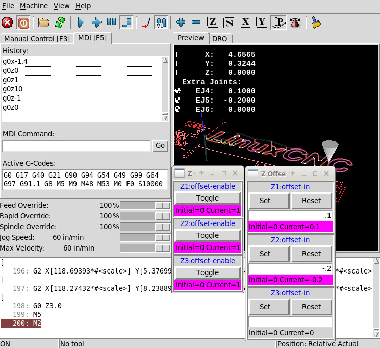
Another suggestion is use of the (new) extrajoints
capabilities available in the master branch. The
extrajoints are homed normally but then use independent
postion control. For slaving multiple spindles, the
extrajoints' position commands are derived from the
commands sent to the joint used for the normal Z coordinate.
Ref: motion man page (master branch):
linuxcnc.org/docs/master/html/man/man9/motion.9.html
The attached config uses 3 extrajoints that follow the
motion of the Z coordinate. Management of height
offsets of these 'following' joints is controlled by
summing individual offsets to the extrajoints'
posthome-cmd pins.
The method is extensible to as many joints as are
available after accomodating the joints used for
kinematics. The master branch supports 16 joints total
so a 4 joint XYZY (gantry) config could add 12 more
'following' extra joints.
Notes:
1) Offsets are applied using a limit3 component so
that velocity/acceleration can be managed to avoid
bumps or following errors when the operator
updates the extrajoints' offsets.
2) The extrajoints velocity/acceleration limits
should match or exceed those for the controlling
joint.
3) Offset management is demonstrated with simple
sim_pin guis but a real application could use a custom
pyvcp panel or jogwheels connected to an encoder counter
followed by a float conversion.
Last edit: 19 Oct 2019 21:57 by dgarrett.
The following user(s) said Thank You: chimeno, tommylight
Please Log in or Create an account to join the conversation.
- Todd Zuercher
-
Topic Author
- Away
- Platinum Member
-
Less
More
- Posts: 4764
- Thank you received: 1464
20 Oct 2019 18:51 #148419
by Todd Zuercher
Replied by Todd Zuercher on topic Custom Kinematics
I loaded your first example config on Friday to make sure it did what I thought it did, and it does.
Since it was in master, I thought I'd give it a play using the new external offsets. It seemed to work ok. I just added a short hal file and a couple of sub programs to make it work. It was certainly easier to setup than what I was using.
I did notice a tiny lag on the slaved axis looking with Halscope. Not sure if it is from thread order or that EO is limited to 0.9 of max velocity. I think I have seen simular lag in my other config. This is one reason I wanted to give a custom kinematics version a try.
Please Log in or Create an account to join the conversation.
- dgarrett
- Offline
- Platinum Member
-
Less
More
- Posts: 492
- Thank you received: 297
20 Oct 2019 19:36 - 21 Oct 2019 15:10 #148422
by dgarrett
The example i would recommend is posted as
forum.linuxcnc.org/38-general-linuxcnc-q...om-kinematics#148368
This method uses extrajoints, not external offsets. None
of the examples posted use external offsets as its
functionality is not applicable to the examples that
i posted. External offsets are added
to coordinate (axis letter) values to modify planned
motion.
Thread order can be important on a real machine.
On real hardware you can place the addf's properly
or adjust their ordring later using the position
argument for addf.
I suspect a hal-only solution will be much simpler
than any custom kinematics method.
Notes:
1)The positon argument for addf is documented only
in its help command as far as i know:
2) The master branch includes a new program 'halreport' that
can be useful for tracking addf ordering:
linuxcnc.org/docs/master/html/hal/tools.html#_halreport
Replied by dgarrett on topic Custom Kinematics
I thought I'd give it a play using the
new external offsets
The example i would recommend is posted as
forum.linuxcnc.org/38-general-linuxcnc-q...om-kinematics#148368
This method uses extrajoints, not external offsets. None
of the examples posted use external offsets as its
functionality is not applicable to the examples that
i posted. External offsets are added
to coordinate (axis letter) values to modify planned
motion.
Thread order can be important on a real machine.
On real hardware you can place the addf's properly
or adjust their ordring later using the position
argument for addf.
I suspect a hal-only solution will be much simpler
than any custom kinematics method.
Notes:
1)The positon argument for addf is documented only
in its help command as far as i know:
$ halrun
halcmd: help addf
addf functname threadname [position]
  Adds function 'functname' to thread 'threadname'.  If
  'position' is specified, adds the function to that spot
  in the thread, otherwise adds it to the end.  Negative
  'position' means position with respect to the end of the
  thread.  For example '1' is start of thread, '-1' is the
  end of the thread, '-3' is third from the end.
2) The master branch includes a new program 'halreport' that
can be useful for tracking addf ordering:
linuxcnc.org/docs/master/html/hal/tools.html#_halreport
Last edit: 21 Oct 2019 15:10 by dgarrett.
The following user(s) said Thank You: Mike_Eitel
Please Log in or Create an account to join the conversation.
- Todd Zuercher
-
Topic Author
- Away
- Platinum Member
-
Less
More
- Posts: 4764
- Thank you received: 1464
21 Oct 2019 12:52 #148466
by Todd Zuercher
Replied by Todd Zuercher on topic Custom Kinematics
Here is my test using External-Offsets. It is just a simple modification of your xyzuvw_v2 example config, with a 2nd hal file and two sub programs added to slave and unslave.
Attachments:
The following user(s) said Thank You: chimeno, tommylight
Please Log in or Create an account to join the conversation.
- dgarrett
- Offline
- Platinum Member
-
Less
More
- Posts: 492
- Thank you received: 297
21 Oct 2019 15:07 - 21 Oct 2019 15:22 #148473
by dgarrett
Replied by dgarrett on topic Custom Kinematics
Excellent and clever. I wrote the code for both
external offsets and extrajoints but didn't
think of your method.
[AXIS_*]OFFSET_AV_RATIO is limiting, you can
modify the the a/v values for the u,v,w coordinates
to match the z coordinate at the ratio limit (since
you are not using planned motion while offsetting
those coordinates).
Example (for ratio of 0.9):
A difference using an extrajoints method is it is can
be a hal-only solution with no slaving subroutines.
Controls for slaving and offsetting could be on
an virtual panel.
external offsets and extrajoints but didn't
think of your method.
If you find the max limit of 0.9 for thenotice a tiny lag on the slaved axis
[AXIS_*]OFFSET_AV_RATIO is limiting, you can
modify the the a/v values for the u,v,w coordinates
to match the z coordinate at the ratio limit (since
you are not using planned motion while offsetting
those coordinates).
Example (for ratio of 0.9):
[AXIS_Z]MAX_VELOCITY     =   39
[AXIS_Z]MAX_ACCELERATION =  100

[AXIS_U]MAX_VELOCITY     =    43.333
[AXIS_U]MAX_ACCELERATION =   111.111
[AXIS_U]OFFSET_AV_RATIO  =    0.9
# similar for corresponding joints
A difference using an extrajoints method is it is can
be a hal-only solution with no slaving subroutines.
Controls for slaving and offsetting could be on
an virtual panel.
Last edit: 21 Oct 2019 15:22 by dgarrett.
The following user(s) said Thank You: tommylight
Please Log in or Create an account to join the conversation.
Time to create page: 0.122 seconds