- LinuxCNC
- General LinuxCNC Questions
- Toshiba VF-S11 VFD for Lathe Spindle - Problems with setup/wiring to 7i76e
Toshiba VF-S11 VFD for Lathe Spindle - Problems with setup/wiring to 7i76e
- denhen89
-
 Topic Author
- Offline
- Elite Member
-

Less
More
- Posts: 301
- Thank you received: 27
16 Jul 2020 14:07 #174849
by denhen89
Toshiba VF-S11 VFD for Lathe Spindle - Problems with setup/wiring to 7i76e was created by denhen89
Hello Guys, my lathe project is almost finished, but since couple of days i am having problems with the VFD setup.
Please do not get me wrong, but i have tried couple different wiring setups, which i think makes no sense to describe them all here but only 2 of them, because i would need to try all those setups again and describe exactly what is happening, so i would really wish you could help me out by checking the TOSHIBA VF-S11 manual: inverterdrive.com/file/toshiba-tosvert-vf-s11-manual
I am using a Mesa 7i76E.
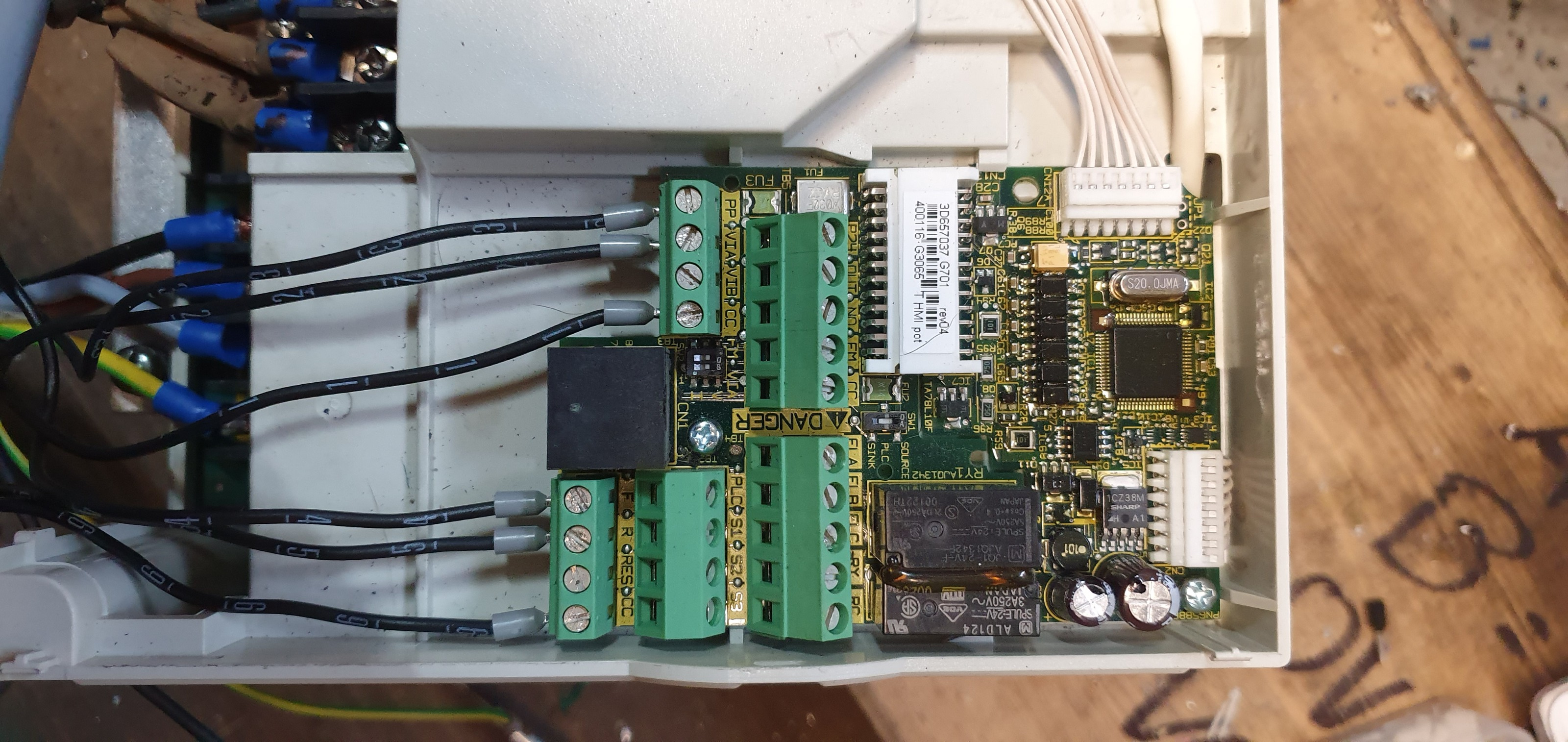
The problem is almost same no matter what wiring setup i am using : On the VFD i can use 2 logics by switching a switch: Source (POSITIVE / Common : P24) and Sink (NEGATIVE / Common: CC)I will give you one example of the wiring setup i tried and tell you what is happening:
Logic: SINK (common: CC terminal pin)
Wiring:
10v to Pin 3
VIA to pin 2
CC to Pin 1
F to Pin 6
R to Pin 8
CC to Pins 7 and 5
What is happening: When starting the spindle on gmoccapy by clicking on the CW Spindle On button (its a lathe so the spindle should turn Counter Clock wise) nothing happens, when clicking the Gmoccapy CCW Button the motor turns, but it goes to max rpm
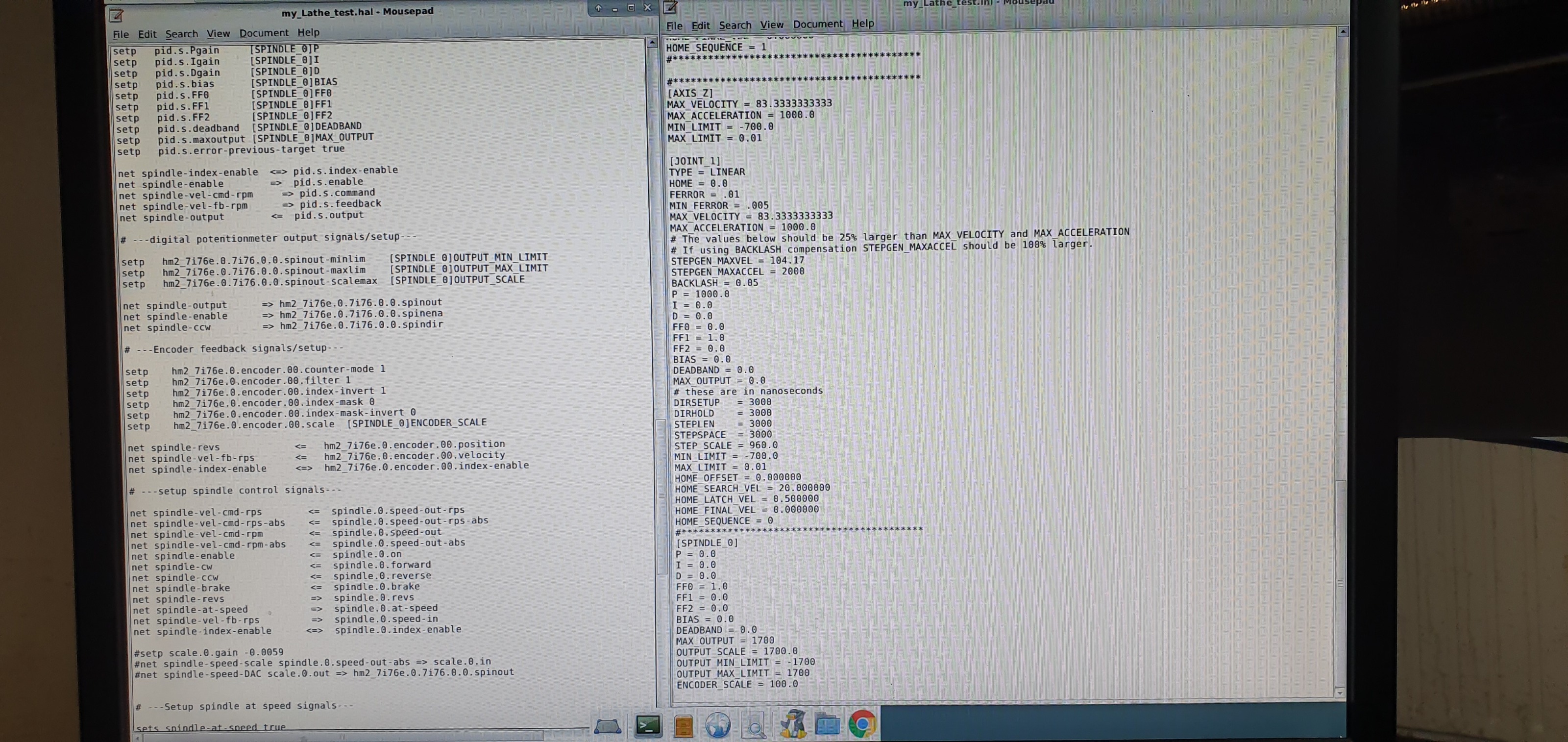
Pictures of wiring setup, HAL and INI setup (sorry that i did not attach the hal file and ini file as i should, but i have some strange network problems on my lathe pc)
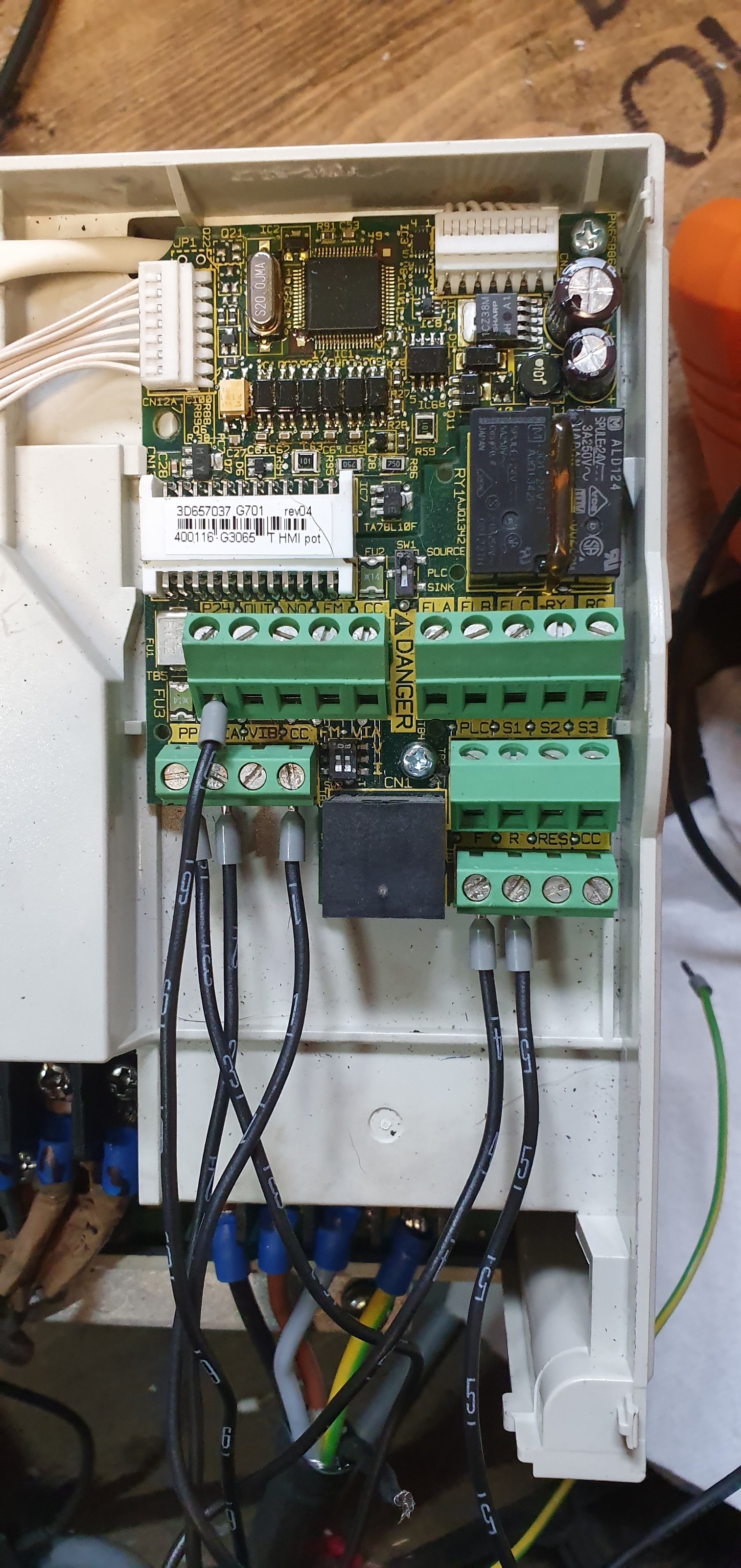
Next try: Source (Positive) Logic (Common: P24)
Wiring:
10v to Pin 3
VIA to pin 2
CC to Pin 1
F to Pin 6
R to Pin 8
P24 to Pins 5 or Pin7, because when both are connect to P24 then nothing happends. If i put P24 to Pin7 instead of Pin5 then the Motor runs in the opposite direction.
The Problem with this wiring: When clicking on the CW spindle On button in Gmoccapy then the spindle runs (almost, because its not scaled perfectly) with the correct speed and the correct direction for my lathe. When clicking on the CCW button, the spindle turns in the same direction and the motor turns to max speed (at 60hz)
Pictures of the wiring setup:
Actually i wanted to use a RS485 to USB adapter to control the spindle speed and direction, but it seems i need some kind of special board for that, so i have no other option than to use the 0-10V analog control method.
I really hope you can help me out again with that problem.
Thanks in advance!
Please do not get me wrong, but i have tried couple different wiring setups, which i think makes no sense to describe them all here but only 2 of them, because i would need to try all those setups again and describe exactly what is happening, so i would really wish you could help me out by checking the TOSHIBA VF-S11 manual: inverterdrive.com/file/toshiba-tosvert-vf-s11-manual
I am using a Mesa 7i76E.
The problem is almost same no matter what wiring setup i am using : On the VFD i can use 2 logics by switching a switch: Source (POSITIVE / Common : P24) and Sink (NEGATIVE / Common: CC)I will give you one example of the wiring setup i tried and tell you what is happening:
Logic: SINK (common: CC terminal pin)
Wiring:
10v to Pin 3
VIA to pin 2
CC to Pin 1
F to Pin 6
R to Pin 8
CC to Pins 7 and 5
What is happening: When starting the spindle on gmoccapy by clicking on the CW Spindle On button (its a lathe so the spindle should turn Counter Clock wise) nothing happens, when clicking the Gmoccapy CCW Button the motor turns, but it goes to max rpm
Pictures of wiring setup, HAL and INI setup (sorry that i did not attach the hal file and ini file as i should, but i have some strange network problems on my lathe pc)
Next try: Source (Positive) Logic (Common: P24)
Wiring:
10v to Pin 3
VIA to pin 2
CC to Pin 1
F to Pin 6
R to Pin 8
P24 to Pins 5 or Pin7, because when both are connect to P24 then nothing happends. If i put P24 to Pin7 instead of Pin5 then the Motor runs in the opposite direction.
The Problem with this wiring: When clicking on the CW spindle On button in Gmoccapy then the spindle runs (almost, because its not scaled perfectly) with the correct speed and the correct direction for my lathe. When clicking on the CCW button, the spindle turns in the same direction and the motor turns to max speed (at 60hz)
Pictures of the wiring setup:
Actually i wanted to use a RS485 to USB adapter to control the spindle speed and direction, but it seems i need some kind of special board for that, so i have no other option than to use the 0-10V analog control method.
I really hope you can help me out again with that problem.
Thanks in advance!
Please Log in or Create an account to join the conversation.
- PCW
-

- Offline
- Moderator
-

Less
More
- Posts: 17985
- Thank you received: 5278
16 Jul 2020 14:40 #174853
by PCW
Replied by PCW on topic Toshiba VF-S11 VFD for Lathe Spindle - Problems with setup/wiring to 7i76e
At least part of the problem is that the hal file is using signed spindle speed
command (spindle-vel-cmd-rpm) instead of a absolute spindle speed
(spindle-vel-cmd-rpm-abs) to set the analog output (which is unsigned)
command (spindle-vel-cmd-rpm) instead of a absolute spindle speed
(spindle-vel-cmd-rpm-abs) to set the analog output (which is unsigned)
Please Log in or Create an account to join the conversation.
- denhen89
-
Topic Author
- Offline
- Elite Member
-
Less
More
- Posts: 301
- Thank you received: 27
16 Jul 2020 14:48 - 16 Jul 2020 14:54 #174855
by denhen89
Replied by denhen89 on topic Toshiba VF-S11 VFD for Lathe Spindle - Problems with setup/wiring to 7i76e
Thanks PCW, but i dont what you actually mean and also i dont know how that should help me with the vfd problem (cw and ccw direction).
I do not see any command that is unsigned, but maybe i do understand something wrong.
Could you please tell me what i should do to solve the problem you are talking about
EDIT: I changed the line: "net spindle-vel-cmd-rpm" to "net spindle-vel-cmd-rpm-abs" for the "pid.s.command"
Now the spindle turns with the same speed , but of course still it turns only in one direction.
Last edit: 16 Jul 2020 14:54 by denhen89.
Please Log in or Create an account to join the conversation.
- PCW
-
- Offline
- Moderator
-
Less
More
- Posts: 17985
- Thank you received: 5278
16 Jul 2020 14:55 - 16 Jul 2020 14:59 #174856
by PCW
Replied by PCW on topic Toshiba VF-S11 VFD for Lathe Spindle - Problems with setup/wiring to 7i76e
The 7I76E analog output is unsigned, but the hal file is connecting it to
a signed rpm value. this will not give the proper analog output for negative
spindle speeds. basically it means that
net spindle-vel-cmd-rpm pid.s.command
needs to be changed to
net spindle-vel-cmd-rpm-abs pid.s.command
Note that thiis is a necessary but probably not complete fix
and you need to get the direction control working also
Last edit: 16 Jul 2020 14:59 by PCW.
The following user(s) said Thank You: denhen89
Please Log in or Create an account to join the conversation.
- denhen89
-
Topic Author
- Offline
- Elite Member
-
Less
More
- Posts: 301
- Thank you received: 27
16 Jul 2020 14:58 #174857
by denhen89
Replied by denhen89 on topic Toshiba VF-S11 VFD for Lathe Spindle - Problems with setup/wiring to 7i76e
Thanks, jus edited my last post, because i changed that line already and now the spindle turns wirth the same speed when clicking on CCW and CW button, but still the motor turns only in one direction, which of course does not suprise me.
There should be some setting in the VFD i think, but i checked the manual already many times and couldnt find anything interesting.
There should be some setting in the VFD i think, but i checked the manual already many times and couldnt find anything interesting.
Please Log in or Create an account to join the conversation.
- PCW
-
- Offline
- Moderator
-
Less
More
- Posts: 17985
- Thank you received: 5278
16 Jul 2020 16:08 - 16 Jul 2020 16:08 #174862
by PCW
Replied by PCW on topic Toshiba VF-S11 VFD for Lathe Spindle - Problems with setup/wiring to 7i76e
Most VFDs have a run/direction option (instead of FWD/REV) but I don't see that for this
particular drive so I suspect you will have to use some 7I76E field outputs to drive FWD and REV
particular drive so I suspect you will have to use some 7I76E field outputs to drive FWD and REV
Last edit: 16 Jul 2020 16:08 by PCW.
Please Log in or Create an account to join the conversation.
- denhen89
-
Topic Author
- Offline
- Elite Member
-
Less
More
- Posts: 301
- Thank you received: 27
16 Jul 2020 16:56 - 16 Jul 2020 16:58 #174866
by denhen89
Replied by denhen89 on topic Toshiba VF-S11 VFD for Lathe Spindle - Problems with setup/wiring to 7i76e
Thanks PCW.
I understand what you mean.
I added this 2 lines:
net spindle-cw hm2_7i76e.0.7i76.0.0.output-04
net spindle-ccw hm2_7i76e.0.7i76.0.0.output-05
(outlined the spindir line)
No i am really confused and do not understand what is going on:
I opened linux after editing the HAL and tested the cw ccw buttons but nothing happend.
Then i shorted CC to F with a wire and somehow both direction worked, so i thought i got it done by your help and wanted to make a bridge between CC and F so that i dont need to hold that wire. When i put the wires back only one direction worked.
Not sure what i have done or why it had worked, but thats my current situation.
PS: On the TB4 i took all wires off and only kept the 3 wires for 0V, 10V and spinout.
Last edit: 16 Jul 2020 16:58 by denhen89.
Please Log in or Create an account to join the conversation.
- PCW
-
- Offline
- Moderator
-
Less
More
- Posts: 17985
- Thank you received: 5278
16 Jul 2020 17:01 - 16 Jul 2020 17:03 #174867
by PCW
Replied by PCW on topic Toshiba VF-S11 VFD for Lathe Spindle - Problems with setup/wiring to 7i76e
You would need to connect CC to 7I76E field common and 7I76E
output 4 to F and output 5 to R (Toshiba manual page B10 right picture)
note the "Slide switch SW1:PLC"
output 4 to F and output 5 to R (Toshiba manual page B10 right picture)
note the "Slide switch SW1:PLC"
Last edit: 16 Jul 2020 17:03 by PCW.
Please Log in or Create an account to join the conversation.
- denhen89
-
Topic Author
- Offline
- Elite Member
-
Less
More
- Posts: 301
- Thank you received: 27
16 Jul 2020 18:05 #174872
by denhen89
Replied by denhen89 on topic Toshiba VF-S11 VFD for Lathe Spindle - Problems with setup/wiring to 7i76e
Thank you PCW for taking your time to help me out.
I tried exactly what you wrote, but unfortunately nothing happends on the motor.
I have took field common from the orange field terminal pin NC (ther two pins next to 0v pin)
I tried exactly what you wrote, but unfortunately nothing happends on the motor.
I have took field common from the orange field terminal pin NC (ther two pins next to 0v pin)
Please Log in or Create an account to join the conversation.
- PCW
-
- Offline
- Moderator
-
Less
More
- Posts: 17985
- Thank you received: 5278
16 Jul 2020 18:09 #174873
by PCW
Replied by PCW on topic Toshiba VF-S11 VFD for Lathe Spindle - Problems with setup/wiring to 7i76e
did you verify that VFD F and R inputs have 24V relative to their CC pin
when the spindle is on? (F or R depending on direction)
when the spindle is on? (F or R depending on direction)
Please Log in or Create an account to join the conversation.
- LinuxCNC
- General LinuxCNC Questions
- Toshiba VF-S11 VFD for Lathe Spindle - Problems with setup/wiring to 7i76e
Time to create page: 0.176 seconds