How to Spindle Synchronized Motion
- Donno
-
 Topic Author
- Offline
- Premium Member
-

- Posts: 137
- Thank you received: 17
Spindle feedback is needed by EMC to perform any spindle coordinated motions like threading and constant surface speed. The StepConf Wizard can perform the connections for you if you select Encoder Phase A and Encoder Index as inputs.
Hardware assumptions:
An encoder is connected to the spindle and puts out 100 pulses per revolution on phase A
The encoder A phase is connected to the parallel port pin 10
The encoder index pulse is connected to the parallel port pin 11
I am currently using the parallel breakout board and the spindle driver manual looks like this :
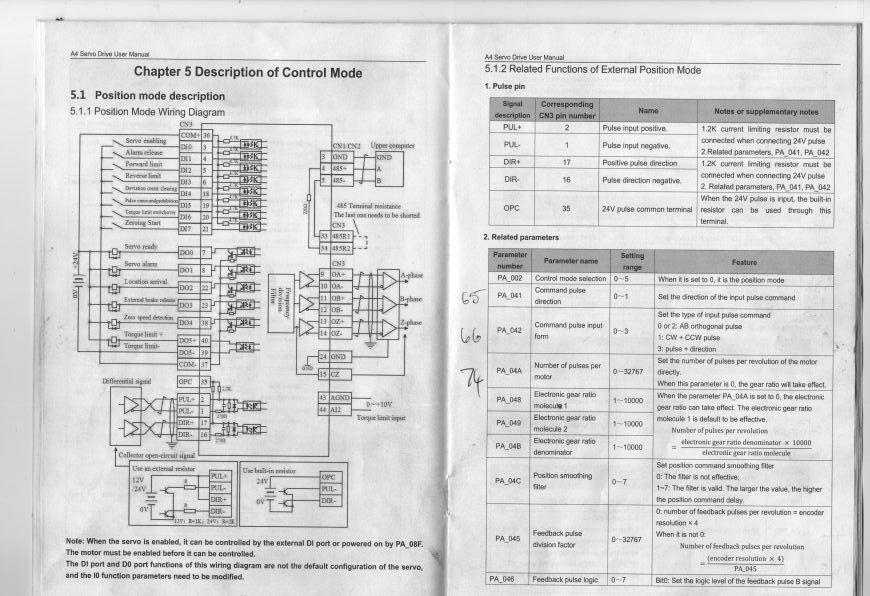
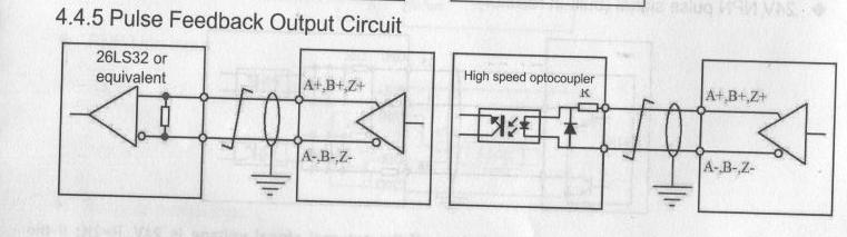
There is a Pulse Feedback output circuit with a Frequency division Filter. I assume the Frequency division Filter can be used to output 100 pulses per revolution to LinuxCNC ?
There is also a circuit to use a 26LS32 to get a Phase Output. Do I connect the output of the 26LS32 to the input pin of the breakout board for each phase ?
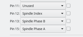
The other question is there are only Phase A , Phase B and Index spindle input pins where would i connect the Spindle index input pin to ?
Any help or explanation on this topic
Please Log in or Create an account to join the conversation.
- andypugh
-

- Offline
- Moderator
-

- Posts: 19886
- Thank you received: 4645
Maybe the only missing piece is that "Z" and "Index" are exactly the same thing?
Please Log in or Create an account to join the conversation.
- Donno
-
Topic Author
- Offline
- Premium Member
-
- Posts: 137
- Thank you received: 17
Attachments:
Please Log in or Create an account to join the conversation.
- andypugh
-
- Offline
- Moderator
-
- Posts: 19886
- Thank you received: 4645
Does the BoB have any information about connecting differential signals?
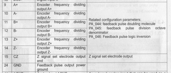
CZ is "Z signal set electrode output end" which is gibberish to me.
I think I would connect pin 24 to the BoB digital GND and then try connecting A+, B+ and Z+ to individual input terminals. If that doesn't work then try the A-, B- Z-.
Use Halscope to check the inputs directly at the p-port driver in LinuxCNC.
Please Log in or Create an account to join the conversation.
- Donno
-
Topic Author
- Offline
- Premium Member
-
- Posts: 137
- Thank you received: 17
After connecting the 26LS32 up with some LEDs the Phase A and Phase B act like a Binary Counter and The Phase Z(Spindle index) will stay on and only switch off and then back on again at a certain position on the motor shaft after making 1 rotation.
Does that behavior sound right?
Please Log in or Create an account to join the conversation.
- andypugh
-
- Offline
- Moderator
-
- Posts: 19886
- Thank you received: 4645
Please Log in or Create an account to join the conversation.
- andypugh
-
- Offline
- Moderator
-
- Posts: 19886
- Thank you received: 4645
Please Log in or Create an account to join the conversation.