Help taming G64 (exact stop). Wildly inaccurate parts right now
- the_wildgoose
- Offline
- New Member
-

Less
More
- Posts: 4
- Thank you received: 0
24 Oct 2020 11:55 #187099
by the_wildgoose
Help taming G64 (exact stop). Wildly inaccurate parts right now was created by the_wildgoose
Hi linuxcnc gurus. I wonder if someone can lend me their experience understanding how to set G64.
My problem right now is with slotting type moves that change height. I had a 2mm endmill and a toolpath programmed in Fusion which literally just slots back and forward some 10mm or so, ramping down 0.5mm on each pass. Nothing crazy, backplot shows it's the right toolpath. Crazy thing is that when I ran it the slot was several mm too short and there was some part cut tabs for the rest of the slot.
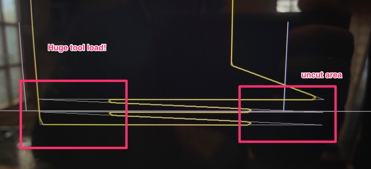
I turned the backplot to look at it in the side on plane and the problem is clear. Fusion has programmed the ramp down to coincide with a direction change. So something like it ramps down into the left most corner of the slot, then it should come to a stop there at the new level and reverse direction and do a complete traverse of the slot at that level. Re-stated, it's ramping down to the right to the new level, once it's at level it traverses to the left at that level. So there is a sharp V shaped corner in the toolpath
However, linuxcnc wants to cut the corner... So some few mm before the ramp down finishes it's horizontal move, linuxcnc starts the acceleration in the opposite direction (completing the vertical ramp in the wrong direction effectively, and missing a few mm of my slot)
I've attached a photo of the path vs the backplot
OK, now adding a G61 obviously cuts the correct toolpath, but then the rest of my program runs very roughly...
I have no idea how to insert G61/G64 into the middle of a fusion360 program (other than opening it up and editing). However, would be interested if anyone has pointers?
I feel it should be possible to set the parameters of G64 to prioritise velocity over path error? Is this as simple as "G64 P0.01"? What are sensible values for Q in that param? Any other tips or pointers with regards to trying to find a single number which will work for "most" of my programs?
With the default settings my paths are several mm incorrect on what feel like pretty slow feed rates (200mm/min or less). Are there any other params that feed into the path planner other than the individual axis accelerations which could be causing this excess rounding?
For reference the machine is a little 6040 alike from Omiocnc. I have my units set in mm and current accelerations are 1000 in x/y and 750 in Z. I've not tried to tune these yet. (are they in the right order of magnitude?)
Wisdom from the experts gratefully received!
My problem right now is with slotting type moves that change height. I had a 2mm endmill and a toolpath programmed in Fusion which literally just slots back and forward some 10mm or so, ramping down 0.5mm on each pass. Nothing crazy, backplot shows it's the right toolpath. Crazy thing is that when I ran it the slot was several mm too short and there was some part cut tabs for the rest of the slot.
I turned the backplot to look at it in the side on plane and the problem is clear. Fusion has programmed the ramp down to coincide with a direction change. So something like it ramps down into the left most corner of the slot, then it should come to a stop there at the new level and reverse direction and do a complete traverse of the slot at that level. Re-stated, it's ramping down to the right to the new level, once it's at level it traverses to the left at that level. So there is a sharp V shaped corner in the toolpath
However, linuxcnc wants to cut the corner... So some few mm before the ramp down finishes it's horizontal move, linuxcnc starts the acceleration in the opposite direction (completing the vertical ramp in the wrong direction effectively, and missing a few mm of my slot)
I've attached a photo of the path vs the backplot
OK, now adding a G61 obviously cuts the correct toolpath, but then the rest of my program runs very roughly...
I have no idea how to insert G61/G64 into the middle of a fusion360 program (other than opening it up and editing). However, would be interested if anyone has pointers?
I feel it should be possible to set the parameters of G64 to prioritise velocity over path error? Is this as simple as "G64 P0.01"? What are sensible values for Q in that param? Any other tips or pointers with regards to trying to find a single number which will work for "most" of my programs?
With the default settings my paths are several mm incorrect on what feel like pretty slow feed rates (200mm/min or less). Are there any other params that feed into the path planner other than the individual axis accelerations which could be causing this excess rounding?
For reference the machine is a little 6040 alike from Omiocnc. I have my units set in mm and current accelerations are 1000 in x/y and 750 in Z. I've not tried to tune these yet. (are they in the right order of magnitude?)
Wisdom from the experts gratefully received!
Attachments:
Please Log in or Create an account to join the conversation.
- Aciera
-

- Offline
- Administrator
-

Less
More
- Posts: 4768
- Thank you received: 2138
24 Oct 2020 12:35 - 24 Oct 2020 12:37 #187100
by Aciera
Replied by Aciera on topic Help taming G64 (exact stop). Wildly inaccurate parts right now
Hm, this looks odd to me. My machine has a max acceleration of 300 and I never had a problem like that running at 200mm/min. Can you post your HAL and INI files?
Also what kind of motors? Is there a feedback coming in like from encoders?
Also what kind of motors? Is there a feedback coming in like from encoders?
Last edit: 24 Oct 2020 12:37 by Aciera.
Please Log in or Create an account to join the conversation.
- Todd Zuercher
-

- Away
- Platinum Member
-

Less
More
- Posts: 4764
- Thank you received: 1464
24 Oct 2020 17:01 #187116
by Todd Zuercher
Replied by Todd Zuercher on topic Help taming G64 (exact stop). Wildly inaccurate parts right now
You may be better off just using G61 in that situation
Please Log in or Create an account to join the conversation.
- the_wildgoose
- Offline
- New Member
-
Less
More
- Posts: 4
- Thank you received: 0
24 Oct 2020 19:49 - 24 Oct 2020 19:53 #187124
by the_wildgoose
Replied by the_wildgoose on topic Help taming G64 (exact stop). Wildly inaccurate parts right now
Hi, thanks for your response. Yes, it's such a large error that I suspect a config issue. You can definitely see from the shape of what it actually did (and that it's perfect with G61) that it's a trajectory optimisation thing, but it feels like it's gone wrong or needs a better G64 config to me?
The machine is using some simple steppers. Here's a link to the manufacturer (it's an above average 6040 type machine)
www.omiocnc.com/products/x6-2200l-usb.html
Main conf files:
The machine is using some simple steppers. Here's a link to the manufacturer (it's an above average 6040 type machine)
www.omiocnc.com/products/x6-2200l-usb.html
Main conf files:
Warning: Spoiler!
# Generated by PNCconf at Tue Feb 25 15:41:32 2020
# Using LinuxCNC version: UNAVAILABLE
# If you make changes to this file, they will be
# overwritten when you run PNCconf again
loadrt [KINS]KINEMATICS
loadrt [EMCMOT]EMCMOT servo_period_nsec=[EMCMOT]SERVO_PERIOD num_joints=[KINS]JOINTS
loadrt hostmot2
loadrt hm2_pci config=" num_encoders=0 num_pwmgens=2 num_stepgens=8"
setp hm2_5i25.0.pwmgen.pwm_frequency 20000
setp hm2_5i25.0.pwmgen.pdm_frequency 6000000
setp hm2_5i25.0.watchdog.timeout_ns 5000000
loadrt pid names=pid.x,pid.y,pid.z,pid.a,pid.s
loadrt abs names=abs.spindle
loadrt lowpass names=lowpass.spindle
addf hm2_5i25.0.read servo-thread
addf motion-command-handler servo-thread
addf motion-controller servo-thread
addf pid.x.do-pid-calcs servo-thread
addf pid.y.do-pid-calcs servo-thread
addf pid.z.do-pid-calcs servo-thread
addf pid.a.do-pid-calcs servo-thread
addf pid.s.do-pid-calcs servo-thread
addf abs.spindle servo-thread
addf lowpass.spindle servo-thread
addf hm2_5i25.0.write servo-thread
# external output signals
# --- MACHINE-IS-ENABLED ---
setp hm2_5i25.0.gpio.001.is_output true
net machine-is-enabled => hm2_5i25.0.gpio.001.out
# --- COOLANT-MIST ---
setp hm2_5i25.0.gpio.007.is_output true
net coolant-mist => hm2_5i25.0.gpio.007.out
# external input signals
# --- MAX-HOME-Z ---
net max-home-z <= hm2_5i25.0.gpio.003.in_not
# --- ESTOP-EXT ---
net estop-ext <= hm2_5i25.0.gpio.013.in
# --- PROBE-IN ---
#net probe-in <= hm2_5i25.0.gpio.014.in_not
net probe-in <= hm2_5i25.0.gpio.014.in
# --- MIN-HOME-X ---
net min-home-x <= hm2_5i25.0.gpio.015.in_not
# --- MAX-HOME-Y ---
net max-home-y <= hm2_5i25.0.gpio.016.in_not
#*******************
# AXIS X JOINT 0
#*******************
setp pid.x.Pgain [JOINT_0]P
setp pid.x.Igain [JOINT_0]I
setp pid.x.Dgain [JOINT_0]D
setp pid.x.bias [JOINT_0]BIAS
setp pid.x.FF0 [JOINT_0]FF0
setp pid.x.FF1 [JOINT_0]FF1
setp pid.x.FF2 [JOINT_0]FF2
setp pid.x.deadband [JOINT_0]DEADBAND
setp pid.x.maxoutput [JOINT_0]MAX_OUTPUT
setp pid.x.error-previous-target true
setp pid.x.maxerror .0005
net x-index-enable <=> pid.x.index-enable
net x-enable => pid.x.enable
net x-pos-cmd => pid.x.command
net x-pos-fb => pid.x.feedback
net x-output <= pid.x.output
# Step Gen signals/setup
setp hm2_5i25.0.stepgen.00.dirsetup [JOINT_0]DIRSETUP
setp hm2_5i25.0.stepgen.00.dirhold [JOINT_0]DIRHOLD
setp hm2_5i25.0.stepgen.00.steplen [JOINT_0]STEPLEN
setp hm2_5i25.0.stepgen.00.stepspace [JOINT_0]STEPSPACE
setp hm2_5i25.0.stepgen.00.position-scale [JOINT_0]STEP_SCALE
setp hm2_5i25.0.stepgen.00.step_type 0
setp hm2_5i25.0.stepgen.00.control-type 1
setp hm2_5i25.0.stepgen.00.maxaccel [JOINT_0]STEPGEN_MAXACCEL
setp hm2_5i25.0.stepgen.00.maxvel [JOINT_0]STEPGEN_MAXVEL
setp hm2_5i25.0.stepgen.00.step.invert_output true
setp hm2_5i25.0.stepgen.00.direction.invert_output true
# ---closedloop stepper signals---
net x-pos-cmd <= joint.0.motor-pos-cmd
net x-vel-cmd <= joint.0.vel-cmd
net x-output <= hm2_5i25.0.stepgen.00.velocity-cmd
net x-pos-fb <= hm2_5i25.0.stepgen.00.position-fb
net x-pos-fb => joint.0.motor-pos-fb
net x-enable <= joint.0.amp-enable-out
net x-enable => hm2_5i25.0.stepgen.00.enable
# ---setup home / limit switch signals---
net min-home-x => joint.0.home-sw-in
net min-home-x => joint.0.neg-lim-sw-in
net x-pos-limit => joint.0.pos-lim-sw-in
#*******************
# AXIS Y JOINT 1
#*******************
setp pid.y.Pgain [JOINT_1]P
setp pid.y.Igain [JOINT_1]I
setp pid.y.Dgain [JOINT_1]D
setp pid.y.bias [JOINT_1]BIAS
setp pid.y.FF0 [JOINT_1]FF0
setp pid.y.FF1 [JOINT_1]FF1
setp pid.y.FF2 [JOINT_1]FF2
setp pid.y.deadband [JOINT_1]DEADBAND
setp pid.y.maxoutput [JOINT_1]MAX_OUTPUT
setp pid.y.error-previous-target true
setp pid.y.maxerror .0005
net y-index-enable <=> pid.y.index-enable
net y-enable => pid.y.enable
net y-pos-cmd => pid.y.command
net y-pos-fb => pid.y.feedback
net y-output <= pid.y.output
# Step Gen signals/setup
setp hm2_5i25.0.stepgen.01.dirsetup [JOINT_1]DIRSETUP
setp hm2_5i25.0.stepgen.01.dirhold [JOINT_1]DIRHOLD
setp hm2_5i25.0.stepgen.01.steplen [JOINT_1]STEPLEN
setp hm2_5i25.0.stepgen.01.stepspace [JOINT_1]STEPSPACE
setp hm2_5i25.0.stepgen.01.position-scale [JOINT_1]STEP_SCALE
setp hm2_5i25.0.stepgen.01.step_type 0
setp hm2_5i25.0.stepgen.01.control-type 1
setp hm2_5i25.0.stepgen.01.maxaccel [JOINT_1]STEPGEN_MAXACCEL
setp hm2_5i25.0.stepgen.01.maxvel [JOINT_1]STEPGEN_MAXVEL
setp hm2_5i25.0.stepgen.01.step.invert_output true
# ---closedloop stepper signals---
net y-pos-cmd <= joint.1.motor-pos-cmd
net y-vel-cmd <= joint.1.vel-cmd
net y-output <= hm2_5i25.0.stepgen.01.velocity-cmd
net y-pos-fb <= hm2_5i25.0.stepgen.01.position-fb
net y-pos-fb => joint.1.motor-pos-fb
net y-enable <= joint.1.amp-enable-out
net y-enable => hm2_5i25.0.stepgen.01.enable
# ---setup home / limit switch signals---
net max-home-y => joint.1.home-sw-in
net y-neg-limit => joint.1.neg-lim-sw-in
net max-home-y => joint.1.pos-lim-sw-in
#*******************
# AXIS Z JOINT 2
#*******************
setp pid.z.Pgain [JOINT_2]P
setp pid.z.Igain [JOINT_2]I
setp pid.z.Dgain [JOINT_2]D
setp pid.z.bias [JOINT_2]BIAS
setp pid.z.FF0 [JOINT_2]FF0
setp pid.z.FF1 [JOINT_2]FF1
setp pid.z.FF2 [JOINT_2]FF2
setp pid.z.deadband [JOINT_2]DEADBAND
setp pid.z.maxoutput [JOINT_2]MAX_OUTPUT
setp pid.z.error-previous-target true
setp pid.z.maxerror .0005
net z-index-enable <=> pid.z.index-enable
net z-enable => pid.z.enable
net z-pos-cmd => pid.z.command
net z-pos-fb => pid.z.feedback
net z-output <= pid.z.output
# Step Gen signals/setup
setp hm2_5i25.0.stepgen.02.dirsetup [JOINT_2]DIRSETUP
setp hm2_5i25.0.stepgen.02.dirhold [JOINT_2]DIRHOLD
setp hm2_5i25.0.stepgen.02.steplen [JOINT_2]STEPLEN
setp hm2_5i25.0.stepgen.02.stepspace [JOINT_2]STEPSPACE
setp hm2_5i25.0.stepgen.02.position-scale [JOINT_2]STEP_SCALE
setp hm2_5i25.0.stepgen.02.step_type 0
setp hm2_5i25.0.stepgen.02.control-type 1
setp hm2_5i25.0.stepgen.02.maxaccel [JOINT_2]STEPGEN_MAXACCEL
setp hm2_5i25.0.stepgen.02.maxvel [JOINT_2]STEPGEN_MAXVEL
setp hm2_5i25.0.stepgen.02.step.invert_output true
# ---closedloop stepper signals---
net z-pos-cmd <= joint.2.motor-pos-cmd
net z-vel-cmd <= joint.2.vel-cmd
net z-output <= hm2_5i25.0.stepgen.02.velocity-cmd
net z-pos-fb <= hm2_5i25.0.stepgen.02.position-fb
net z-pos-fb => joint.2.motor-pos-fb
net z-enable <= joint.2.amp-enable-out
net z-enable => hm2_5i25.0.stepgen.02.enable
# ---setup home / limit switch signals---
net max-home-z => joint.2.home-sw-in
net z-neg-limit => joint.2.neg-lim-sw-in
net max-home-z => joint.2.pos-lim-sw-in
#*******************
# AXIS A JOINT 3
#*******************
setp pid.a.Pgain [JOINT_3]P
setp pid.a.Igain [JOINT_3]I
setp pid.a.Dgain [JOINT_3]D
setp pid.a.bias [JOINT_3]BIAS
setp pid.a.FF0 [JOINT_3]FF0
setp pid.a.FF1 [JOINT_3]FF1
setp pid.a.FF2 [JOINT_3]FF2
setp pid.a.deadband [JOINT_3]DEADBAND
setp pid.a.maxoutput [JOINT_3]MAX_OUTPUT
setp pid.a.error-previous-target true
setp pid.a.maxerror .0005
net a-index-enable <=> pid.a.index-enable
net a-enable => pid.a.enable
net a-pos-cmd => pid.a.command
net a-pos-fb => pid.a.feedback
net a-output <= pid.a.output
# Step Gen signals/setup
setp hm2_5i25.0.stepgen.03.dirsetup [JOINT_3]DIRSETUP
setp hm2_5i25.0.stepgen.03.dirhold [JOINT_3]DIRHOLD
setp hm2_5i25.0.stepgen.03.steplen [JOINT_3]STEPLEN
setp hm2_5i25.0.stepgen.03.stepspace [JOINT_3]STEPSPACE
setp hm2_5i25.0.stepgen.03.position-scale [JOINT_3]STEP_SCALE
setp hm2_5i25.0.stepgen.03.step_type 0
setp hm2_5i25.0.stepgen.03.control-type 1
setp hm2_5i25.0.stepgen.03.maxaccel [JOINT_3]STEPGEN_MAXACCEL
setp hm2_5i25.0.stepgen.03.maxvel [JOINT_3]STEPGEN_MAXVEL
setp hm2_5i25.0.stepgen.03.step.invert_output true
# ---closedloop stepper signals---
net a-pos-cmd <= joint.3.motor-pos-cmd
net a-vel-cmd <= joint.3.vel-cmd
net a-output <= hm2_5i25.0.stepgen.03.velocity-cmd
net a-pos-fb <= hm2_5i25.0.stepgen.03.position-fb
net a-pos-fb => joint.3.motor-pos-fb
net a-enable <= joint.3.amp-enable-out
net a-enable => hm2_5i25.0.stepgen.03.enable
# ---setup home / limit switch signals---
#net max-home-a => joint.3.home-sw-in
#net a-neg-limit => joint.3.neg-lim-sw-in
#net max-home-a => joint.3.pos-lim-sw-in
#******************************
# connect miscellaneous signals
#******************************
# ---HALUI signals---
net axis-select-x halui.axis.x.select
net jog-x-pos halui.axis.x.plus
net jog-x-neg halui.axis.x.minus
net jog-x-analog halui.axis.x.analog
net x-is-homed halui.joint.0.is-homed
net axis-select-y halui.axis.y.select
net jog-y-pos halui.axis.y.plus
net jog-y-neg halui.axis.y.minus
net jog-y-analog halui.axis.y.analog
net y-is-homed halui.joint.1.is-homed
net axis-select-z halui.axis.z.select
net jog-z-pos halui.axis.z.plus
net jog-z-neg halui.axis.z.minus
net jog-z-analog halui.axis.z.analog
net z-is-homed halui.joint.2.is-homed
net jog-selected-pos halui.axis.selected.plus
net jog-selected-neg halui.axis.selected.minus
net spindle-manual-cw halui.spindle.0.forward
net spindle-manual-ccw halui.spindle.0.reverse
net spindle-manual-stop halui.spindle.0.stop
net machine-is-on halui.machine.is-on
net jog-speed halui.axis.jog-speed
net MDI-mode halui.mode.is-mdi
# ---coolant signals---
net coolant-mist <= iocontrol.0.coolant-mist
net coolant-flood <= iocontrol.0.coolant-flood
# ---probe signal---
net probe-in => motion.probe-input
# ---motion control signals---
net in-position <= motion.in-position
net machine-is-enabled <= motion.motion-enabled
# ---digital in / out signals---
# ---estop signals---
net estop-out <= iocontrol.0.user-enable-out
net estop-ext => iocontrol.0.emc-enable-in
# ---manual tool change signals---
loadusr -W hal_manualtoolchange
net tool-change-request iocontrol.0.tool-change => hal_manualtoolchange.change
net tool-change-confirmed iocontrol.0.tool-changed <= hal_manualtoolchange.changed
net tool-number iocontrol.0.tool-prep-number => hal_manualtoolchange.number
net tool-prepare-loopback iocontrol.0.tool-prepare => iocontrol.0.tool-prepared
Warning: Spoiler!
# Generated by PNCconf at Tue Feb 25 15:41:32 2020
# Using LinuxCNC version: UNAVAILABLE
# If you make changes to this file, they will be
# overwritten when you run PNCconf again
[EMC]
MACHINE = omio_x6_5abob
DEBUG = 0
VERSION = 1.1
[DISPLAY]
DISPLAY = probe_basic
OPEN_FILE = ~/dev/probe_basic/example_gcode/blank.ngc
# Command Line Args
CONFIRM_EXIT = False
CONFIG_FILE = custom_config.yml
;FULLSCREEN = True
;MAXIMIZE = True
POSITION = 0x0
POSITION_OFFSET = RELATIVE
POSITION_FEEDBACK = ACTUAL
MAX_FEED_OVERRIDE = 2.000000
MAX_SPINDLE_OVERRIDE = 2.000000
MIN_SPINDLE_OVERRIDE = 0.500000
DEFAULT_SPINDLE_SPEED = 300
INTRO_GRAPHIC = linuxcnc.gif
INTRO_TIME = 1
# File Paths:
# File paths can be relative to the config dir:
# LOG_FILE = qtpyvcp.log
# Or relative to $HOME: (May not be compatible with other GUIs!)
# LOG_FILE = ~/qtpyvcp.log
# Or at an absolute location:
# LOG_FILE = /home/<USER>/qtpyvcp.log
# Enviroment vars are also expanded:
# LOG_FILE = $CONFIG_DIR/qtpyvcp.log
LOG_FILE = sim.log
PREFERENCE_FILE = ui.pref
PROGRAM_PREFIX = ~/linuxcnc/nc_files
INCREMENTS = JOG 1mm .1mm .05mm .01mm .001mm
DEFAULT_LINEAR_VELOCITY = 50.000000
MAX_LINEAR_VELOCITY = 120.000000
MIN_LINEAR_VELOCITY = 0.500000
DEFAULT_ANGULAR_VELOCITY = 70.000000
MAX_ANGULAR_VELOCITY = 360.000000
MIN_ANGULAR_VELOCITY = 1.666667
GEOMETRY = xyza
MAX_SPINDLE_SPEED = 24000
[VTK]
# VTK_Widget Options
;MACHINE_BOUNDRY = True
;MACHINE_TICKS = True
;MACHINE_LABELS = True
;PROGRAM_BOUNDRY = False
;PROGRAM_TICKS = False
;PROGRAM_LABELS = False
;GRID_LINES = True
[FILTER]
PROGRAM_EXTENSION = .nc,.txt,.tap Other NC files
PROGRAM_EXTENSION = .png,.gif,.jpg Greyscale Depth Image
;PROGRAM_EXTENSION = .py Python Script
png = image-to-gcode
gif = image-to-gcode
jpg = image-to-gcode
py = python
[TASK]
TASK = milltask
CYCLE_TIME = 0.010
[RS274NGC]
PARAMETER_FILE = linuxcnc.var
;RS274NGC_STARTUP_CODE = F10 S300 G21 G17 G40 G49 G54 G64 P0.001 G80 G90 G91.1 G92.1 G94 G97 G98
FEATURES = 30
SUBROUTINE_PATH = ~/probe_basic/config/probe_basic/subroutines
[EMCMOT]
EMCMOT = motmod
COMM_TIMEOUT = 1.0
SERVO_PERIOD = 1000000
[HMOT]
# **** This is for info only ****
CARD0=hm2_5i25.0
[HAL]
HALUI = halui
HALFILE = omio_x6_5abob.hal
HALFILE = custom.hal
POSTGUI_HALFILE = postgui_call_list.hal
POSTGUI_HALFILE = hallib/time.hal
SHUTDOWN = shutdown.hal
[HALUI]
[KINS]
JOINTS = 4
KINEMATICS = trivkins coordinates=XYZA
[TRAJ]
COORDINATES = XYZA
LINEAR_UNITS = mm
ANGULAR_UNITS = degree
DEFAULT_LINEAR_VELOCITY = 10.00
MAX_LINEAR_VELOCITY = 100.00
NO_FORCE_HOMING = 1
SPINDLES = 1
[EMCIO]
EMCIO = io
CYCLE_TIME = 0.100
TOOL_TABLE = tool.tbl
TOOL_CHANGE_QUILL_UP = 1
#******************************************
[AXIS_X]
MAX_VELOCITY = 100.0
MAX_ACCELERATION = 1000
MIN_LIMIT = -0.01
MAX_LIMIT = 355.0
[JOINT_0]
TYPE = LINEAR
HOME = 0.0
FERROR = 1.0
MIN_FERROR = 0.01
MAX_VELOCITY = 100.0
MAX_ACCELERATION = 1000.0
# The values below should be 25% larger than MAX_VELOCITY and MAX_ACCELERATION
# If using BACKLASH compensation STEPGEN_MAXACCEL should be 100% larger.
STEPGEN_MAXVEL = 125.00
STEPGEN_MAXACCEL = 1250
P = 1000.0
I = 0.0
D = 0.0
FF0 = 0.0
FF1 = 1.0
FF2 = 0.0
BIAS = 0.0
DEADBAND = 0.0
MAX_OUTPUT = 0.0
# these are in nanoseconds
DIRSETUP = 10000
DIRHOLD = 10000
STEPLEN = 5000
STEPSPACE = 5000
# moves 19.945 for 20mm commanded move
#STEP_SCALE = 321.2679
STEP_SCALE = 320.6
MIN_LIMIT = -0.01
MAX_LIMIT = 355.0
HOME_OFFSET = -5.000000
HOME_SEARCH_VEL = -50
HOME_LATCH_VEL = 0.500000
HOME_FINAL_VEL = 33.333333
HOME_USE_INDEX = NO
HOME_IGNORE_LIMITS = YES
HOME_SEQUENCE = 1
#******************************************
#******************************************
[AXIS_Y]
MAX_VELOCITY = 100.0
MAX_ACCELERATION = 1000.0
MIN_LIMIT = -510.0
MAX_LIMIT = 0.01
[JOINT_1]
TYPE = LINEAR
HOME = 0.0
FERROR = 1.0
MIN_FERROR = 0.01
MAX_VELOCITY = 100.0
MAX_ACCELERATION = 1000.0
# The values below should be 25% larger than MAX_VELOCITY and MAX_ACCELERATION
# If using BACKLASH compensation STEPGEN_MAXACCEL should be 100% larger.
STEPGEN_MAXVEL = 125.00
STEPGEN_MAXACCEL = 1250.0
P = 1000.0
I = 0.0
D = 0.0
FF0 = 0.0
FF1 = 1.0
FF2 = 0.0
BIAS = 0.0
DEADBAND = 0.0
MAX_OUTPUT = 0.0
# these are in nanoseconds
DIRSETUP = 10000
DIRHOLD = 10000
STEPLEN = 5000
STEPSPACE = 5000
STEP_SCALE = 320
MIN_LIMIT = -510.0
MAX_LIMIT = 0.01
HOME_OFFSET = 2.000000
HOME_SEARCH_VEL = 50
HOME_LATCH_VEL = -0.500000
HOME_FINAL_VEL = 33.333333
HOME_USE_INDEX = NO
HOME_IGNORE_LIMITS = YES
HOME_SEQUENCE = 2
#******************************************
#******************************************
[AXIS_Z]
MAX_VELOCITY = 50.0
MAX_ACCELERATION = 750.0
MIN_LIMIT = -140.0
MAX_LIMIT = 0.01
[JOINT_2]
TYPE = LINEAR
HOME = 0.0
FERROR = 1.0
MIN_FERROR = 0.01
MAX_VELOCITY = 50.0
MAX_ACCELERATION = 750.0
# The values below should be 25% larger than MAX_VELOCITY and MAX_ACCELERATION
# If using BACKLASH compensation STEPGEN_MAXACCEL should be 100% larger.
STEPGEN_MAXVEL = 62.50
STEPGEN_MAXACCEL = 937.50
P = 1000.0
I = 0.0
D = 0.0
FF0 = 0.0
FF1 = 1.0
FF2 = 0.0
BIAS = 0.0
DEADBAND = 0.0
MAX_OUTPUT = 0.0
# these are in nanoseconds
DIRSETUP = 10000
DIRHOLD = 10000
STEPLEN = 5000
STEPSPACE = 5000
STEP_SCALE = 80.0
MIN_LIMIT = -140.0
MAX_LIMIT = 0.01
HOME_OFFSET = 2.000000
HOME_SEARCH_VEL = 50
HOME_LATCH_VEL = -0.500000
HOME_FINAL_VEL = 33.333333
HOME_USE_INDEX = NO
HOME_IGNORE_LIMITS = YES
HOME_SEQUENCE = 0
#******************************************
#******************************************
[AXIS_A]
MAX_VELOCITY = 70.0
MAX_ACCELERATION = 1000.0
MIN_LIMIT = -1e99
MAX_LIMIT = 1e99
WRAPPED_ROTARY = 0
[JOINT_3]
TYPE = ANGULAR
HOME = 0.0
FERROR = 1.0
MIN_FERROR = 0.01
MAX_VELOCITY = 70.0
MAX_ACCELERATION = 1000.0
# The values below should be 25% larger than MAX_VELOCITY and MAX_ACCELERATION
# If using BACKLASH compensation STEPGEN_MAXACCEL should be 100% larger.
STEPGEN_MAXVEL = 100.00
STEPGEN_MAXACCEL = 1250.00
P = 1000.0
I = 0.0
D = 0.0
FF0 = 0.0
FF1 = 1.0
FF2 = 0.0
BIAS = 0.0
DEADBAND = 0.0
MAX_OUTPUT = 0.0
# these are in nanoseconds
DIRSETUP = 10000
DIRHOLD = 10000
STEPLEN = 5000
STEPSPACE = 5000
STEP_SCALE = 111.111111
MIN_LIMIT = -1e99
MAX_LIMIT = 1e99
HOME_OFFSET = 0.000000
HOME_SEARCH_VEL = 0
HOME_LATCH_VEL = 0
HOME_FINAL_VEL = 0
HOME_USE_INDEX = NO
HOME_IGNORE_LIMITS = YES
HOME_SEQUENCE = 99
#******************************************
[SPINDLE_0]
MAX_OUTPUT = 24000.0
Last edit: 24 Oct 2020 19:53 by the_wildgoose.
Please Log in or Create an account to join the conversation.
- Todd Zuercher
-
- Away
- Platinum Member
-
Less
More
- Posts: 4764
- Thank you received: 1464
25 Oct 2020 02:00 #187155
by Todd Zuercher
Replied by Todd Zuercher on topic Help taming G64 (exact stop). Wildly inaccurate parts right now
Is Fusion using G64 with no P tolerance? If so that equals maximum path blending with no tolerance. Using A G64 P0.01 or an even smaller P value will help immensely.
There is no reason you can't insert G61 and G64Pnn commands anywhere within a g-code file. Changing from one to another is allowed and will not cause any problems. But you would likely have to insert them by hand with a text editor. I've not run into any CAM program that could do it automatically.
It is often a big enough challenge just to get them to insert the right one at the start of the file once.
Please Log in or Create an account to join the conversation.
- the_wildgoose
- Offline
- New Member
-
Less
More
- Posts: 4
- Thank you received: 0
25 Oct 2020 13:44 #187189
by the_wildgoose
Replied by the_wildgoose on topic Help taming G64 (exact stop). Wildly inaccurate parts right now
Actually the default output from the CAM doesn't include any G64/G61 at all, so it's whatever I have at that moment on my machine. Temporarily I have been splitting my program up into 2 parts and running each with different settings (or hand editing the pre-amble at the top of the file.
So yes, it's definitely using a straight G64 no P tolerance. Can you guide me on setting a reasonable P value (and Q?) though? Why is the error quite so far out without any P tolerance??
It seems like I should be able to accelerate this machine more closely within the tolerances than showed up in the backplot vs actual here? I feel that the machine has done something like connecting the Z and X velocities and it's trying to get the X direction reversal done within the Z travel remaining, hence it's got to abort the move early. However, even then it feels like it's also got some large tolerance that it's working in, since surely it could get that move done closer to the end of the point??
If I use G64 P0.01, does that mean that it will track to within 0.01 of the pointy end of that toolpath? Presumably then compromising on velocity if needed in order to hit the required toolpath? Are there any obvious negatives to this (on soft materials such as aluminium)? ie is it sensible to set a default machine pre-amble to G64 P0.01?
As an aside, it took me until this error to realise what was wrong with all my engraving toolpaths... They all looked a bit wobbly before and the ends of letters like capital L were very slightly truncated. G61 and they are now perfect. I guess because I was rapiding out of the stroke, linuxcnc was trying to blend that move into the toolpath move and hence rounding the ends of the stroke. Simple once you realise what is going on...
Please Log in or Create an account to join the conversation.
- Todd Zuercher
-
- Away
- Platinum Member
-
Less
More
- Posts: 4764
- Thank you received: 1464
25 Oct 2020 15:36 #187200
by Todd Zuercher
Replied by Todd Zuercher on topic Help taming G64 (exact stop). Wildly inaccurate parts right now
Without a p tolerance the rounding can consume up to half of the shorter of the 2 segments or whatever allows the machine to maintain the programed federate with your acceleration setting.
I'm not sure exactly how the tolerance works but I believe it is the distance from the end point where the blending arc begins. So the measured deviation will be a bit less.
I'm not sure exactly how the tolerance works but I believe it is the distance from the end point where the blending arc begins. So the measured deviation will be a bit less.
Please Log in or Create an account to join the conversation.
- Todd Zuercher
-
- Away
- Platinum Member
-
Less
More
- Posts: 4764
- Thank you received: 1464
26 Oct 2020 12:56 #187303
by Todd Zuercher
Replied by Todd Zuercher on topic Help taming G64 (exact stop). Wildly inaccurate parts right now
Also the default setting in Linuxcnc when you first turn it on is G64 with no P. It is an extremely good idea to include a G64 command with an appropriate P tolerance in the preamble of all of your g-code files.
On our wood carving routers running in inches mode I use G64P0.005. For a metal milling machine P=0.0001 might be more appropriate (or P=0.0025 on a metric machine.) It is often a good idea to experiment a bit to find the right balance of speed and accuracy. You might find a large P value is best for roughing passes (to maintain a more constant feed rate), then use a small P for the finish pass to hold a tighter tolerance.
Also having low acceleration limits programmed in the machine configuration will exacerbate the problem. So don't be too conservative when choosing them.
Please Log in or Create an account to join the conversation.
Time to create page: 0.111 seconds