MESA 7i77 Encoder Wiring 24V
- danielehrhardt
- Offline
- New Member
-

Less
More
- Posts: 1
- Thank you received: 0
14 Nov 2020 15:55 #189343
by danielehrhardt
MESA 7i77 Encoder Wiring 24V was created by danielehrhardt
Hello,
we are currently a bit stuck with the wiring of our old Bautz Motor Encoder.
I attached an Image with the Datasheet of the Motor+Encoder. The Encoder was attached to a 24V DC Power Supply in the old Machine.
We attached on our Mesa Card a 24V DC Power Supply at TB2 (Field Power).
We used a Multimeter to measure the 24V at the TB3/Encoder 0, but we are not able to get the Voltage only 5V DC like described in the Manual of the Card.
We know that we have:
1 QA0 TO 7I77
2 /QA0 TO 7I77
3 GND FROM 7I77
4 QB0 TO 7I77
5 /QB0 TO 7I77
6 +5V FROM 7I77
7 IDX0 TO 7I77
8 /IDX0 TO 7I77
And 4 Wired from the Encoder, but we are currently not 100% sure how to attach them. We do not want to destroy the Mesa Card.
Do we need to add a second Power Supply for the Encoders and attach the Power Supply external not over the Mesa Card?
Maybe someone could help.
Manual 7I77:
mesanet.com/pdf/parallel/7i77man.pdf
Best,
Daniel
Please Log in or Create an account to join the conversation.
- PCW
-

- Away
- Moderator
-

Less
More
- Posts: 17997
- Thank you received: 5284
14 Nov 2020 16:17 - 14 Nov 2020 16:19 #189344
by PCW
Replied by PCW on topic MESA 7i77 Encoder Wiring 24V
The 7I77 is intended for 5V signal encoders and can supply 5V to these encoders
What is the signal level on you encoder outputs? If these are more than 5V,
they cannot connect directly to the 7I77 encoder inputs
BTW your drawing shows 5V encoder power. If you connect 24V to a 5V encoder,
you will likely destroy it
What is the signal level on you encoder outputs? If these are more than 5V,
they cannot connect directly to the 7I77 encoder inputs
BTW your drawing shows 5V encoder power. If you connect 24V to a 5V encoder,
you will likely destroy it
Last edit: 14 Nov 2020 16:19 by PCW.
Please Log in or Create an account to join the conversation.
- JensWeber
- Offline
- New Member
-
Less
More
- Posts: 5
- Thank you received: 1
14 Nov 2020 17:03 #189348
by JensWeber
Replied by JensWeber on topic MESA 7i77 Encoder Wiring 24V
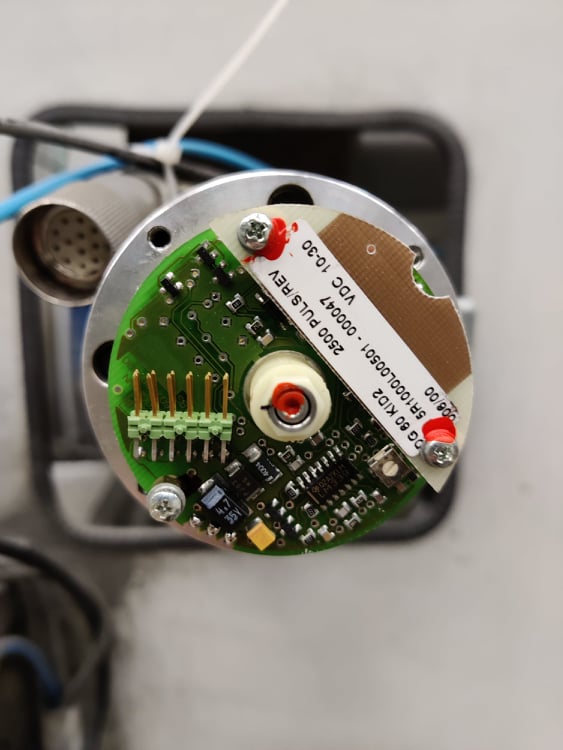
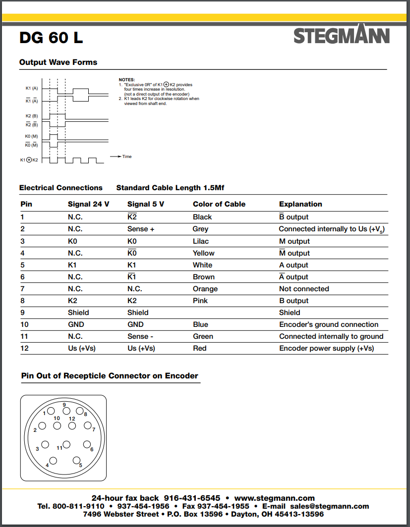
Hello, i work together with Daniel. The drawing shows 5V, but if we open the encoders enclosure its 24V, also the old machine controlers had 24V encoder power. Our Encoder has 4 wires:
black/white= GND and shielding
yellow= 24V power
UA1 = 2-5v signal
UA2 = 2-5v signal
so between UA1 and UA2 we have 5 V thats ok, but if i measure UA1/UA2 against GND i have the 24V.
black/white= GND and shielding
yellow= 24V power
UA1 = 2-5v signal
UA2 = 2-5v signal
so between UA1 and UA2 we have 5 V thats ok, but if i measure UA1/UA2 against GND i have the 24V.
Please Log in or Create an account to join the conversation.
- JensWeber
- Offline
- New Member
-
Less
More
- Posts: 5
- Thank you received: 1
14 Nov 2020 17:04 #189349
by JensWeber
Replied by JensWeber on topic MESA 7i77 Encoder Wiring 24V
Attachments:
Please Log in or Create an account to join the conversation.
- JensWeber
- Offline
- New Member
-
Less
More
- Posts: 5
- Thank you received: 1
14 Nov 2020 17:45 - 14 Nov 2020 17:46 #189352
by JensWeber
Replied by JensWeber on topic MESA 7i77 Encoder Wiring 24V
I think this could be our encoder. It seems 25V or 5V is possible.

Last edit: 14 Nov 2020 17:46 by JensWeber.
Please Log in or Create an account to join the conversation.
- tommylight
-

- Offline
- Moderator
-
Less
More
- Posts: 21767
- Thank you received: 7439
14 Nov 2020 18:30 #189359
by tommylight
Replied by tommylight on topic MESA 7i77 Encoder Wiring 24V
If that picture is of your actual encoder, do not wire that to 7i77.
The PDF shows different versions of the same encoder, does not say it can be used as a 5 and 24V one.
You can use voltage dividers on the encoder outputs, that would require 2 resistors for each encoder output, but be warned that any disconnect in the voltage divider can and will destroy 7i77 encoder inputs.
Personally, i did use a 7i77 with voltage dividers, it is still in use daily after 3 or 4 years.
Please Log in or Create an account to join the conversation.
- JensWeber
- Offline
- New Member
-
Less
More
- Posts: 5
- Thank you received: 1
14 Nov 2020 19:22 - 14 Nov 2020 19:23 #189368
by JensWeber
Replied by JensWeber on topic MESA 7i77 Encoder Wiring 24V
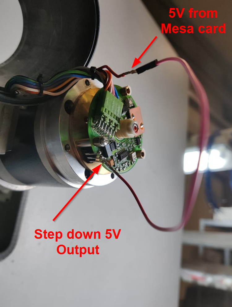
I found out there was a TA7805S voltage regulator. i bridged this regulator, now the encoder gives me 5V signals.
Attachments:
Last edit: 14 Nov 2020 19:23 by JensWeber.
Please Log in or Create an account to join the conversation.
- tommylight
-
- Offline
- Moderator
-
Less
More
- Posts: 21767
- Thank you received: 7439
14 Nov 2020 20:11 #189370
by tommylight
Replied by tommylight on topic MESA 7i77 Encoder Wiring 24V
....or you can do that ! ")
Please Log in or Create an account to join the conversation.
- JensWeber
- Offline
- New Member
-
Less
More
- Posts: 5
- Thank you received: 1
14 Nov 2020 23:07 #189403
by JensWeber
Replied by JensWeber on topic MESA 7i77 Encoder Wiring 24V
Thanks for your help
The following user(s) said Thank You: tommylight
Please Log in or Create an account to join the conversation.
Time to create page: 0.213 seconds