Ohmic probe wiring diagram
- radek_marko
- Offline
- Senior Member
-

Less
More
- Posts: 73
- Thank you received: 18
17 Apr 2021 10:05 #206168
by radek_marko
Ohmic probe wiring diagram was created by radek_marko
Hi,
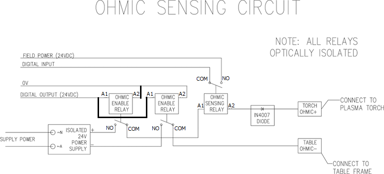
I'm preparing hardware for the ohmic probe for my plasma machine and I have found that this wiring diagram:
linuxcnc.org/docs/devel/html/plasma/plas...r.html#ohmic-sensing
linuxcnc.org/docs/devel/html/plasma/imag...er_ohmic-sensing.png
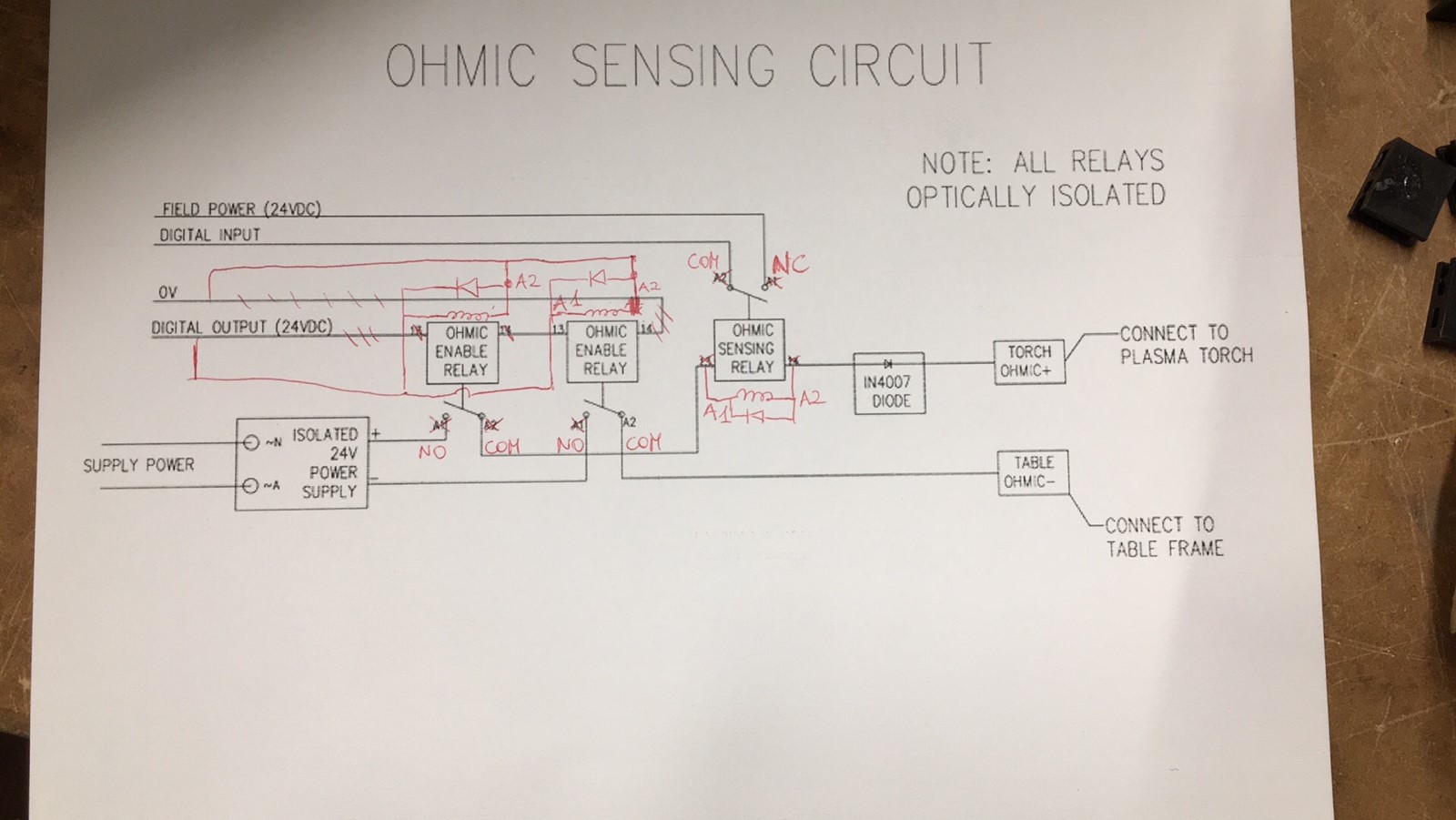
I think markings on this diagram are slightly misleading. I'm attaching a diagram that I have prepared. The marking A1 / A2 are usually for the coil side of the relay. Pins 11 / 14 are usually for NO (Normally Open) and COM (COMmon).
Also, coils for probe enabled were connected in series, I think if two relays are used they should be in parallel.
In my system, I have used a single dual-channel relay to enable/disable the probe.
Modifed diagram:
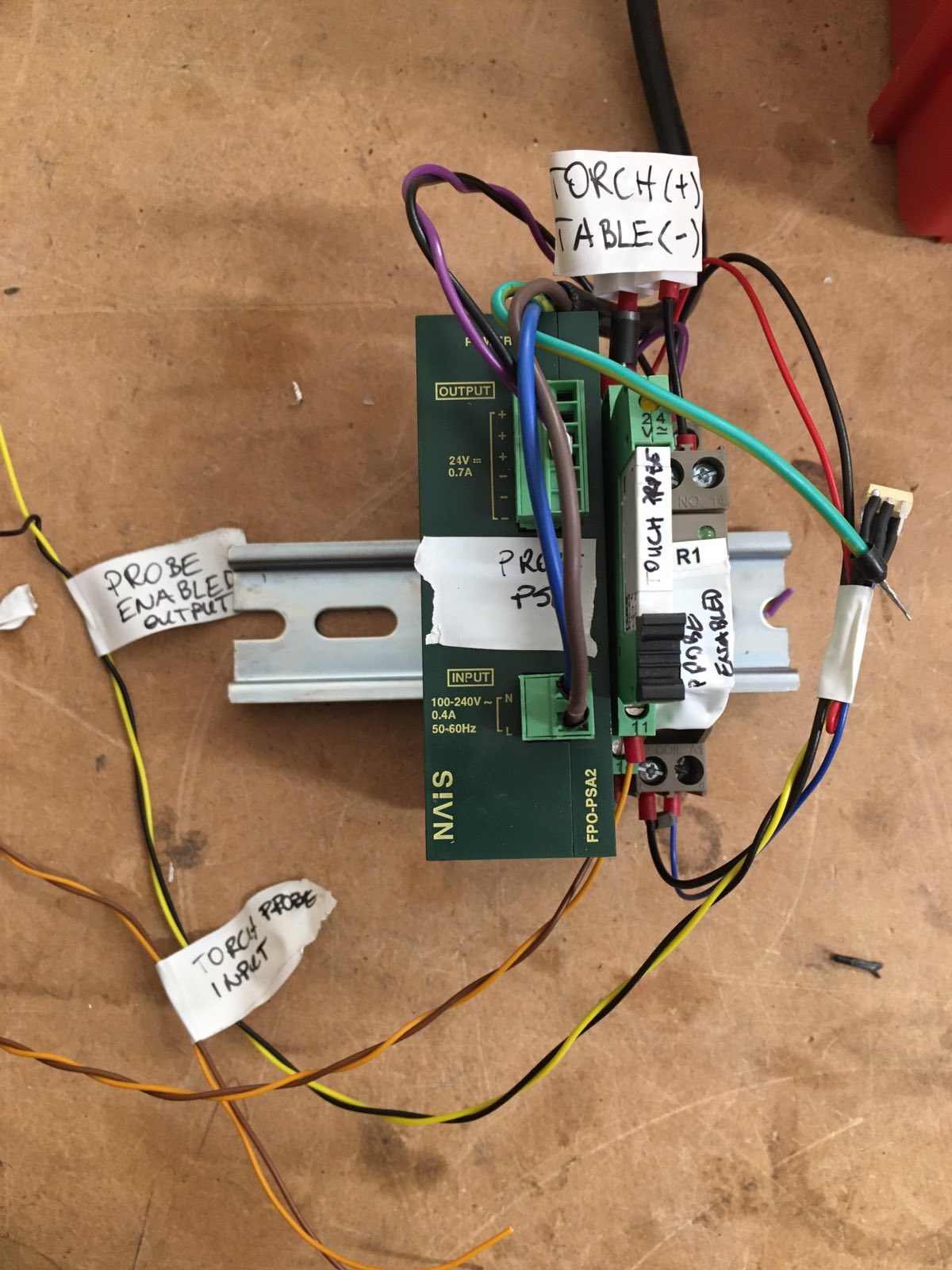
My scrible notes and photos of my unit:
I'm preparing hardware for the ohmic probe for my plasma machine and I have found that this wiring diagram:
linuxcnc.org/docs/devel/html/plasma/plas...r.html#ohmic-sensing
linuxcnc.org/docs/devel/html/plasma/imag...er_ohmic-sensing.png
I think markings on this diagram are slightly misleading. I'm attaching a diagram that I have prepared. The marking A1 / A2 are usually for the coil side of the relay. Pins 11 / 14 are usually for NO (Normally Open) and COM (COMmon).
Also, coils for probe enabled were connected in series, I think if two relays are used they should be in parallel.
In my system, I have used a single dual-channel relay to enable/disable the probe.
Modifed diagram:
My scrible notes and photos of my unit:
Attachments:
The following user(s) said Thank You: txtrone
Please Log in or Create an account to join the conversation.
- rodw
-

- Offline
- Platinum Member
-

Less
More
- Posts: 12014
- Thank you received: 4097
17 Apr 2021 10:55 - 17 Apr 2021 10:56 #206172
by rodw
Replied by rodw on topic Ohmic probe wiring diagram
I do agree with the relays should be in parallel.
Note that the original circuit was contributed by theislander261 (John) and specified the use of opto isolated relays for additional protection (he used an opto22 module) Note point 4 in the primer.Using Opto isolated relays is to provide an additional level of protection as if something goes wrong the torch voltage could jump mechanical relay contacts...
Whilst the temptation is to use a single dual channel relay, this does not provide a significant level of protection in our view. ( I can say our view as the primer includes input from a number of users).
So if Opto isolated relays are used, there is no need for flyback diodes.
For your own safety, I would recommend that you replace you relay with opto isolated ones. (I am assuming you are using a mechanical relay as you have suggested the use of flyback diodes)
Of course an updated diagram via a pull request would be welcome!
Note that the original circuit was contributed by theislander261 (John) and specified the use of opto isolated relays for additional protection (he used an opto22 module) Note point 4 in the primer.
Both sides of the circuit needs to be isolated by opto-isolated relays until probing is being undertakenWhilst the temptation is to use a single dual channel relay, this does not provide a significant level of protection in our view. ( I can say our view as the primer includes input from a number of users).
So if Opto isolated relays are used, there is no need for flyback diodes.
For your own safety, I would recommend that you replace you relay with opto isolated ones. (I am assuming you are using a mechanical relay as you have suggested the use of flyback diodes)
Of course an updated diagram via a pull request would be welcome!
Last edit: 17 Apr 2021 10:56 by rodw.
Please Log in or Create an account to join the conversation.
- radek_marko
- Offline
- Senior Member
-
Less
More
- Posts: 73
- Thank you received: 18
17 Apr 2021 11:28 #206177
by radek_marko
Replied by radek_marko on topic Ohmic probe wiring diagram
Thank you for the advice.
If you take a look closer at my application I have trans-optor on the dual-channel relay (white 4N35 module with 1.5k resistor on the diode side). The single-channel relay will connect to my MESA 7i96 board input - already opto-isolated.
If you take a look closer at my application I have trans-optor on the dual-channel relay (white 4N35 module with 1.5k resistor on the diode side). The single-channel relay will connect to my MESA 7i96 board input - already opto-isolated.
The following user(s) said Thank You: txtrone
Please Log in or Create an account to join the conversation.
- txtrone
-

- Offline
- Platinum Member
-
Less
More
- Posts: 384
- Thank you received: 106
18 Apr 2021 01:54 #206257
by txtrone
Replied by txtrone on topic Ohmic probe wiring diagram
You sound like you know a bit about electronics. Thanks for posting schematics
Please Log in or Create an account to join the conversation.
- radek_marko
- Offline
- Senior Member
-
Less
More
- Posts: 73
- Thank you received: 18
18 Apr 2021 12:17 #206299
by radek_marko
Replied by radek_marko on topic Ohmic probe wiring diagram
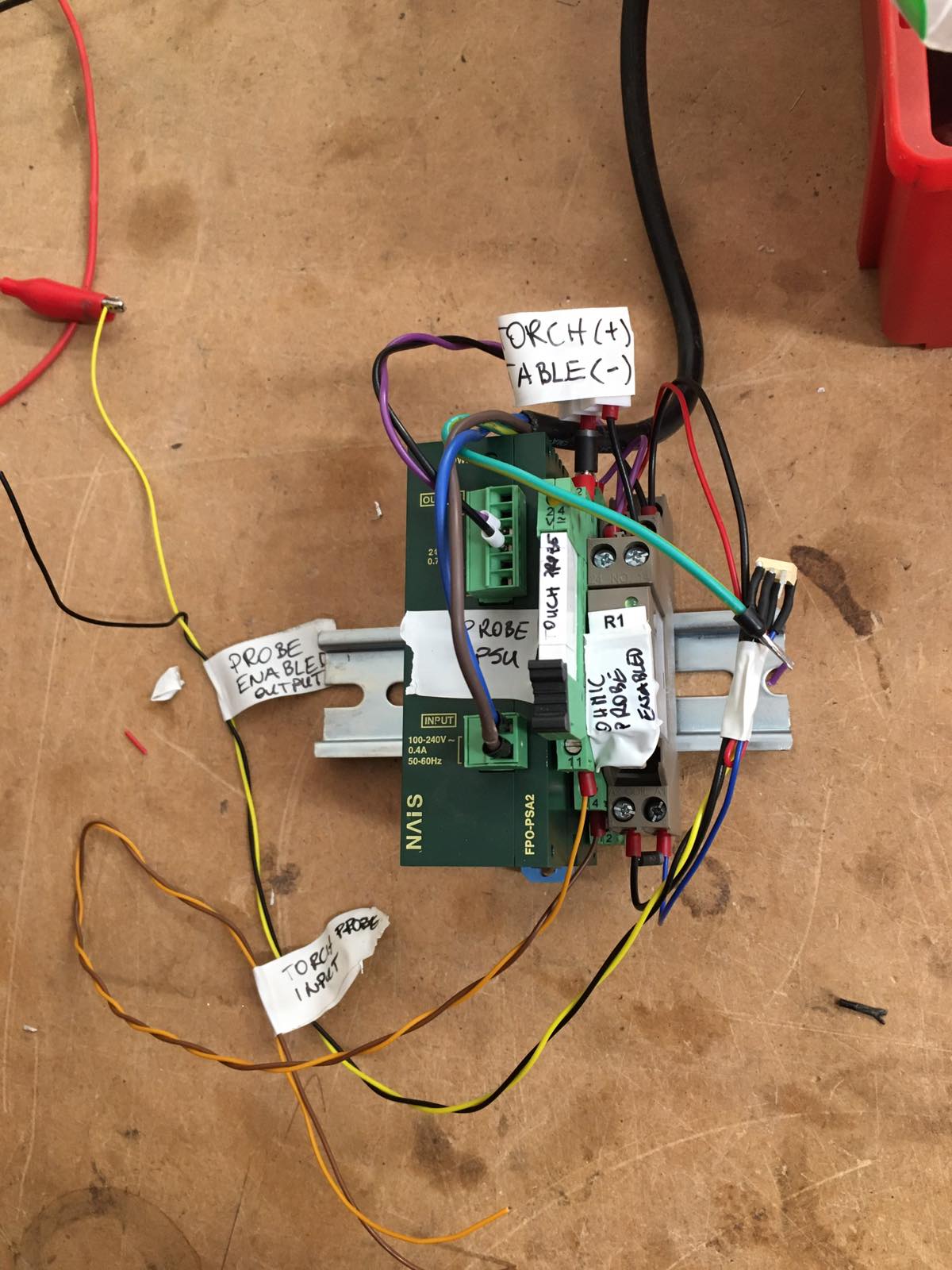
Ohmic probe installed:
The following user(s) said Thank You: rodw, txtrone
Please Log in or Create an account to join the conversation.
- txtrone
-
- Offline
- Platinum Member
-
Less
More
- Posts: 384
- Thank you received: 106
18 Apr 2021 15:49 #206311
by txtrone
Replied by txtrone on topic Ohmic probe wiring diagram
Good work!
Please Log in or Create an account to join the conversation.
- santy
- Offline
- Premium Member
-

Less
More
- Posts: 117
- Thank you received: 10
24 Sep 2023 14:06 #281546
by santy
Replied by santy on topic Ohmic probe wiring diagram
Hey! Sorry to revive the topic, but im trying to built this aswell.
I have got one from a vietnamese store but it just doesn't work after a while!
I want to build my own.
Could you please state the relays and diodes, condensers used please?
thank you
I have got one from a vietnamese store but it just doesn't work after a while!
I want to build my own.
Could you please state the relays and diodes, condensers used please?
thank you
Please Log in or Create an account to join the conversation.
- rodw
-
- Offline
- Platinum Member
-
Less
More
- Posts: 12014
- Thank you received: 4097
24 Sep 2023 20:27 #281561
by rodw
Replied by rodw on topic Ohmic probe wiring diagram
Its covered here
linuxcnc.org/docs/2.9/html/plasma/plasma...itial_height_sensing
linuxcnc.org/docs/2.9/html/plasma/plasma...itial_height_sensing
Please Log in or Create an account to join the conversation.
- HaroldHarvey
- Offline
- New Member
-

Less
More
- Posts: 2
- Thank you received: 1
28 Sep 2023 07:41 - 01 Dec 2025 13:41 #281773
by HaroldHarvey
Replied by HaroldHarvey on topic Ohmic probe wiring diagram
Thanks for the response.
Last edit: 01 Dec 2025 13:41 by HaroldHarvey.
Please Log in or Create an account to join the conversation.
Time to create page: 0.369 seconds