- LinuxCNC
- General LinuxCNC Questions
- LinuxCNC parsing G code shows that the tool path is inconsistent with CAM
LinuxCNC parsing G code shows that the tool path is inconsistent with CAM
- jess
- Offline
- New Member
-

- Posts: 10
- Thank you received: 1
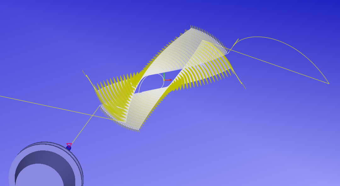
This is the path I verified in CIMCO_Edit software:
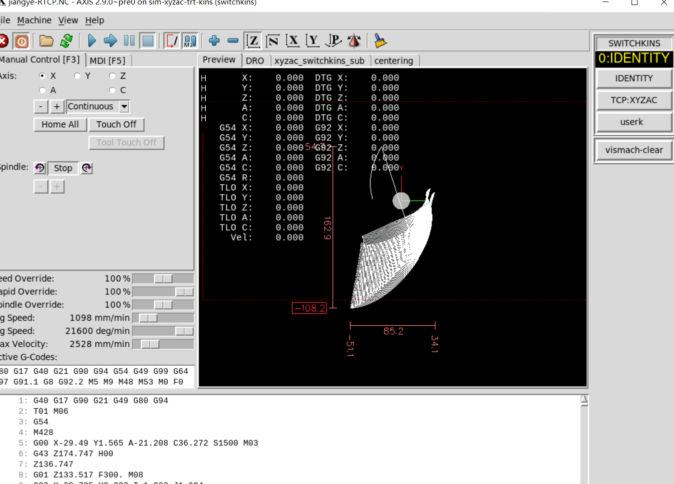
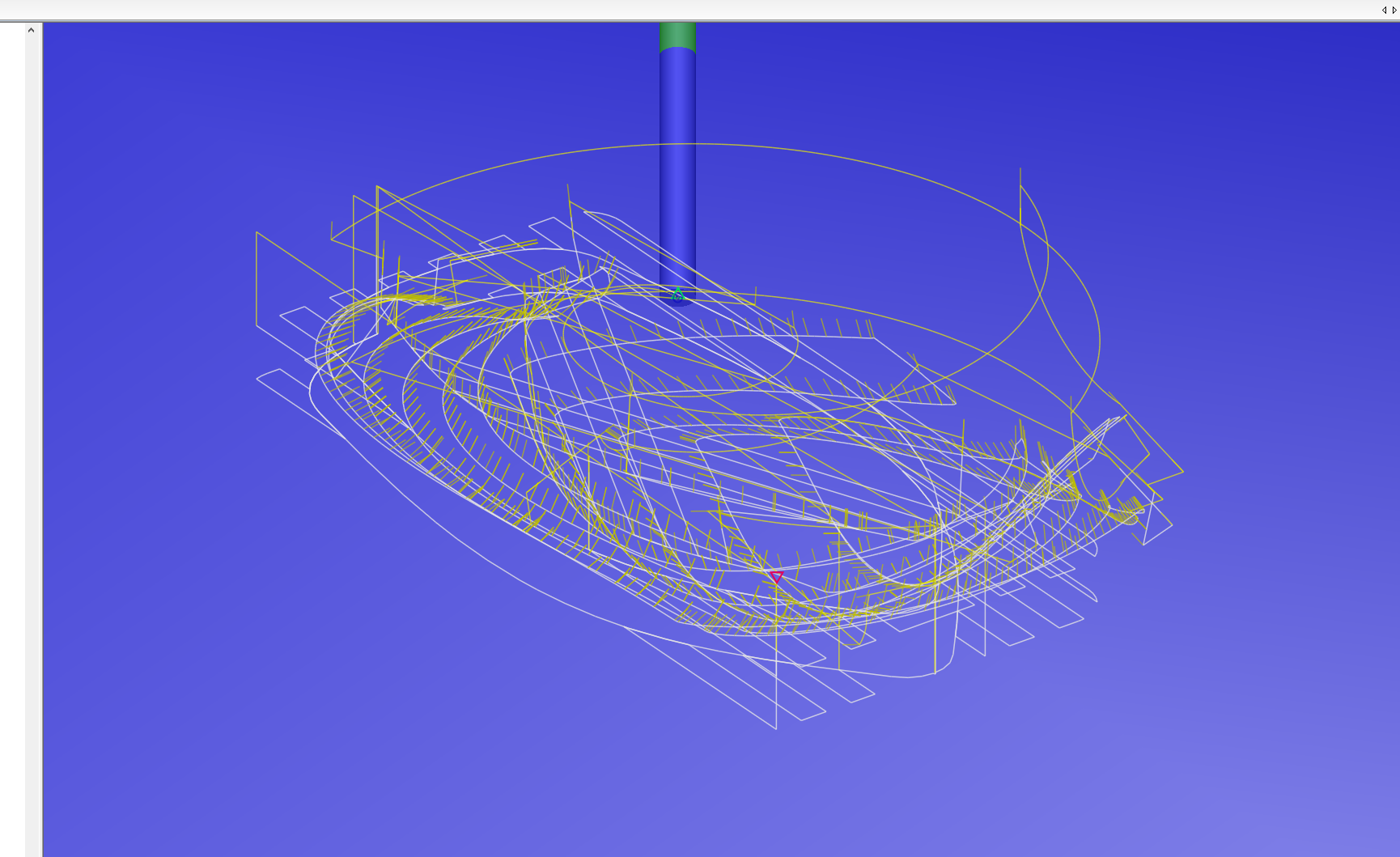
This is the tool path generated in LinuxCNC:
This is my G code:
Attachments:
Please Log in or Create an account to join the conversation.
- Grotius
-

- Offline
- Platinum Member
-

- Posts: 2419
- Thank you received: 2344
Please Log in or Create an account to join the conversation.
- jess
- Offline
- New Member
-

- Posts: 10
- Thank you received: 1
Please Log in or Create an account to join the conversation.
- tommylight
-

- Away
- Moderator
-

- Posts: 20925
- Thank you received: 7132
Please Log in or Create an account to join the conversation.
- jess
- Offline
- New Member
-

- Posts: 10
- Thank you received: 1
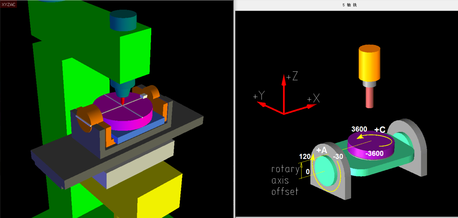
I installed version 2.9So I ran the xyzac Kinematics directly in version 2.9The configuration in INI looks like this:There are 5 joints in that screenshot, how are your axis set in the ini file, display and traj section ?
[DISPLAY]
            GEOMETRY = XYZ-A
           OPEN_FILE = ./demos/xyzac_switchkins.ngc
               PYVCP = ./xyzac-trt.xml
            JOG_AXES = XYZC
             DISPLAY = axis
MAX_ANGULAR_VELOCITY =  360
 MAX_LINEAR_VELOCITY = 1000
     POSITION_OFFSET = RELATIVE
   POSITION_FEEDBACK = ACTUAL
   MAX_FEED_OVERRIDE = 2
      PROGRAM_PREFIX = ../../nc_files
       INTRO_GRAPHIC = emc2.gif
          INTRO_TIME = 1
             #EDITOR = gedit
         TOOL_EDITOR = tooledit z diam

               TKPKG = Ngcgui 1.0
         NGCGUI_FONT = Helvetica -12 normal
      NGCGUI_SUBFILE = xyzac_switchkins_sub.ngc
NGCGUI_SUBFILE = centering.ngc[TRAJ]
COORDINATES = XYZAC
LINEAR_UNITS = mm
ANGULAR_UNITS = deg
DEFAULT_LINEAR_VELOCITY = 20
MAX_LINEAR_VELOCITY = 35
MAX_LINEAR_ACCELERATION = 400
DEFAULT_LINEAR_ACCELERATION = 300Please Log in or Create an account to join the conversation.
- jess
- Offline
- New Member
-

- Posts: 10
- Thank you received: 1
Attachments:
Please Log in or Create an account to join the conversation.
- Aciera
-

- Offline
- Administrator
-

- Posts: 4565
- Thank you received: 2031
The only idea I can come up with to maybe find out what is wrong is to turn the workflow around and import the demo file /sim/axis/vismach/5axis/table-rotary-tilting/demos/boat-xyzac.ngc into CimcoEdit and see what that looks like. Likely it will not look as it should using your present settings so you will need to adjust those settings until you get a correct toolpath for the demo file and then use those in your CAM/PostProcessor.
Sadly there has been a lack of user feedback regarding 5axis machining which has greatly hindered development in this area.
So all feedback is welcome!
[edit]
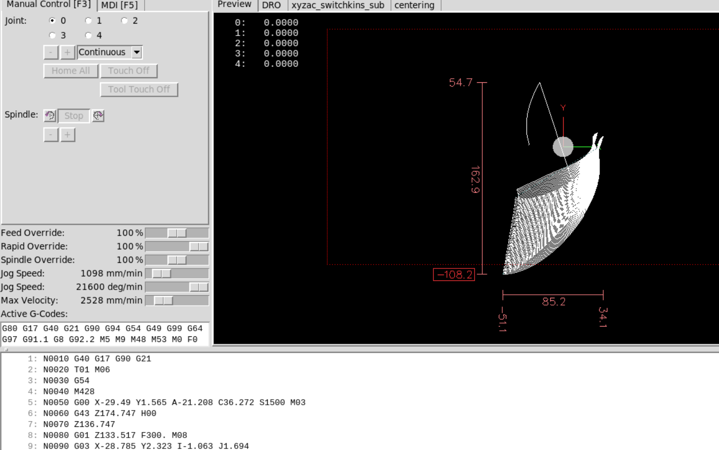
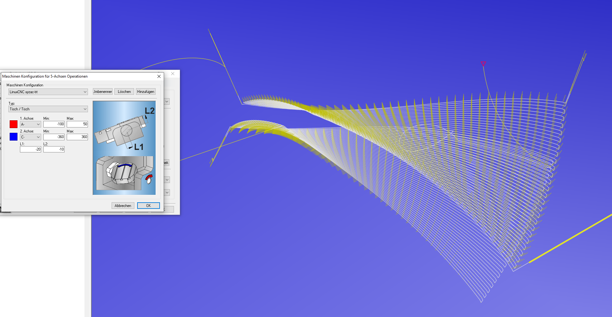
I did a quick test using the settings as seen in the screen shot that seem to give a reasonable backplot for your code:
And here the boat-xyzac.ngc which is clearly not happy with the same settings:
[2.edit]
Also note that, as has been recently suggested, the rotation direction in the 'xyzac-trt' and 'xyzbc-trt' kinematic might be opposite to the standard definition in that positive rotation is in reference to the machine coordinate system and not in respect to the tool. But since the original author has not been heard from for several years and only sporadic feedback trickles from users who may or may not be competent the question has not been resolved.
[3. edit]
Just dawned on me that you are probably using trivial code (ie the kinematics was calculated in the CAM, while the boat-xyzac.ngc file is TCP code. So my approach above might not very useful.
But maybe this thread contains something of interest:
forum.linuxcnc.org/38-general-linuxcnc-q...aneous-setup-in-lcnc
Attachments:
Please Log in or Create an account to join the conversation.
- Grotius
-

- Offline
- Platinum Member
-

- Posts: 2419
- Thank you received: 2344
I tested the gcode and the preview seems ok to me.
user-images.githubusercontent.com/448801...948-8af0d7c784f9.mp4
Please Log in or Create an account to join the conversation.
- jess
- Offline
- New Member
-

- Posts: 10
- Thank you received: 1
Thank you for your test, but the result is not correct, the two ends of the blade are disjointI attached a screenshot of my model to make it easier to understandGrotius post=232906 userid=23278嗨,我测试了 gcode,预览对我来说似乎还可以。https://user-images.githubusercontent.com/44880102/150702166-d3bb010b-47d7-4201-b948-8af0d7c784f9.mp4Thank you for your test, but the result is not correct, the two ends of the blade are disjointI have attached a demo of my model to make it easier to understand
Please Log in or Create an account to join the conversation.
- jess
- Offline
- New Member
-

- Posts: 10
- Thank you received: 1
Thank you for your suggestions and reference links, which are very useful to me. I will give feedback as soon as there is any progress hereAciera post=232641 用户 ID=25994在我看来,您的 CAM/后处理器/CimcoEdit 中有一些设置与 LinuxCNC 中的“xyzac-trt”运动学不一致。
我能想出的唯一可能找出问题所在的想法是扭转工作流程并将演示文件 /sim/axis/vismach/5axis/table-rotary-tilting/demos/boat-xyzac.ngc 导入 CimcoEdit看看那是什么样子。使用您当前的设置,它可能看起来不像它应该的那样,因此您需要调整这些设置,直到您为演示文件获得正确的刀具路径,然后在您的 CAM/PostProcessor 中使用这些设置。
遗憾的是,缺乏有关 5 轴加工的用户反馈,这极大地阻碍了该领域的发展。
因此,欢迎所有反馈!
[编辑]
我使用屏幕截图中的设置进行了快速测试,这些设置似乎为您的代码提供了合理的背景图:
这里的boat-xyzac.ngc 显然不开心使用相同的设置:
[2.edit]
另请注意,正如最近建议的那样,“xyzac-trt”和“xyzbc-trt”运动学中的旋转方向可能与标准定义相反,正旋转是相对于机器坐标系而不是相对于刀具。但由于原作者已有数年没有收到任何消息,并且只有来自可能或可能不称职的用户的零星反馈,因此问题尚未得到解决。
[3. 编辑]
我刚刚意识到您可能正在使用微不足道的代码(即运动学是在 CAM 中计算的,而boat-xyzac.ngc 文件是 TCP 代码。所以我上面的方法可能不是很有用。
但也许这个线程包含一些有趣的东西:
https ://forum.linuxcnc.org/38-general-linuxcnc-questions/35855-question-5axis-simultaneous-setup-in-lcnc
Please Log in or Create an account to join the conversation.
- LinuxCNC
- General LinuxCNC Questions
- LinuxCNC parsing G code shows that the tool path is inconsistent with CAM

