Hello,
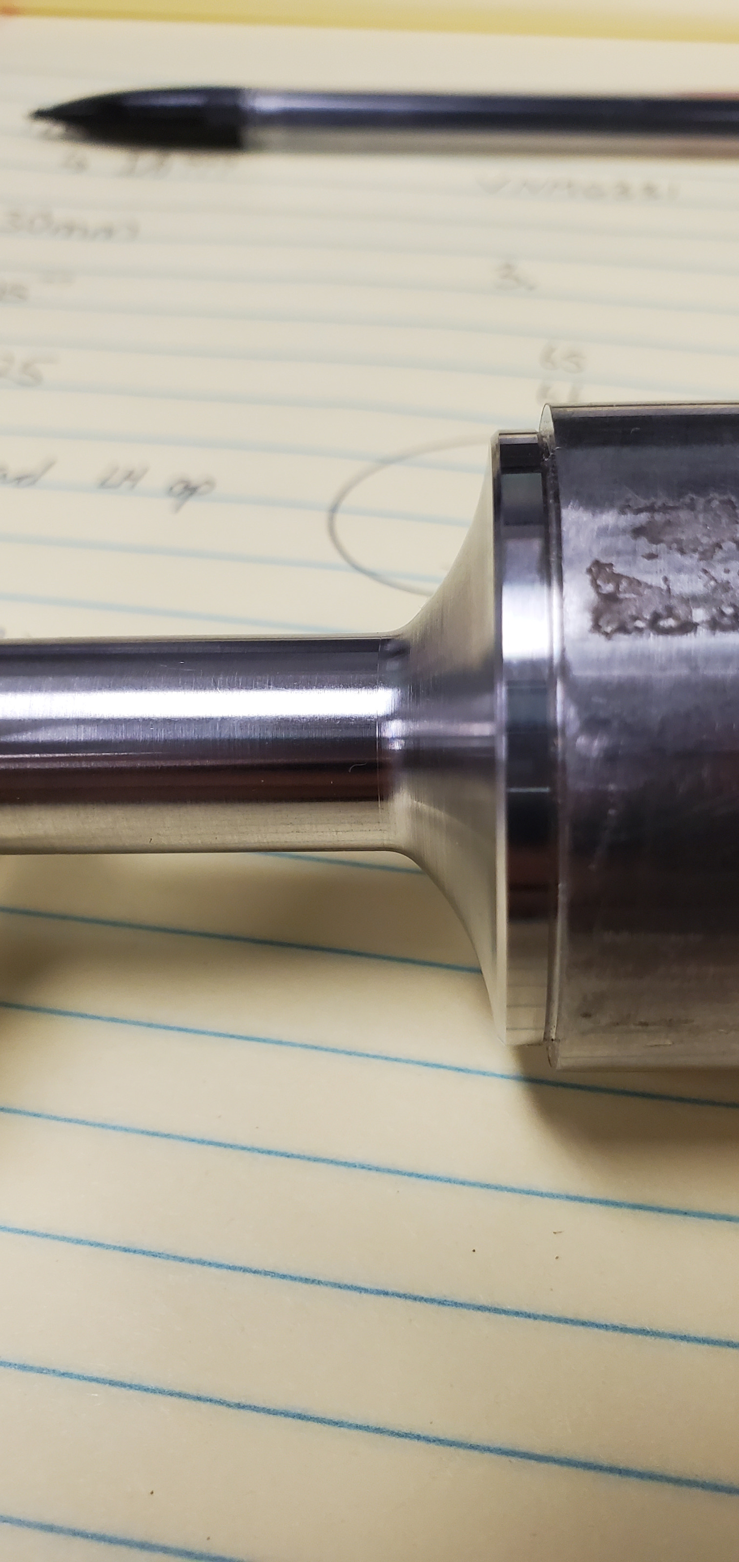
I am having difficulty achieving tolerance machining a .750" +/-.005" radius. My lathe has stepper motors with micro-stepping drives, Mesa FPGA and daughtercard. I have measured x and z axis ball screw backlash and entered compensation values(both are less than .001"). The lathe has been able to consistently achieve /-.001" tolerances on diameters and Z lengths.
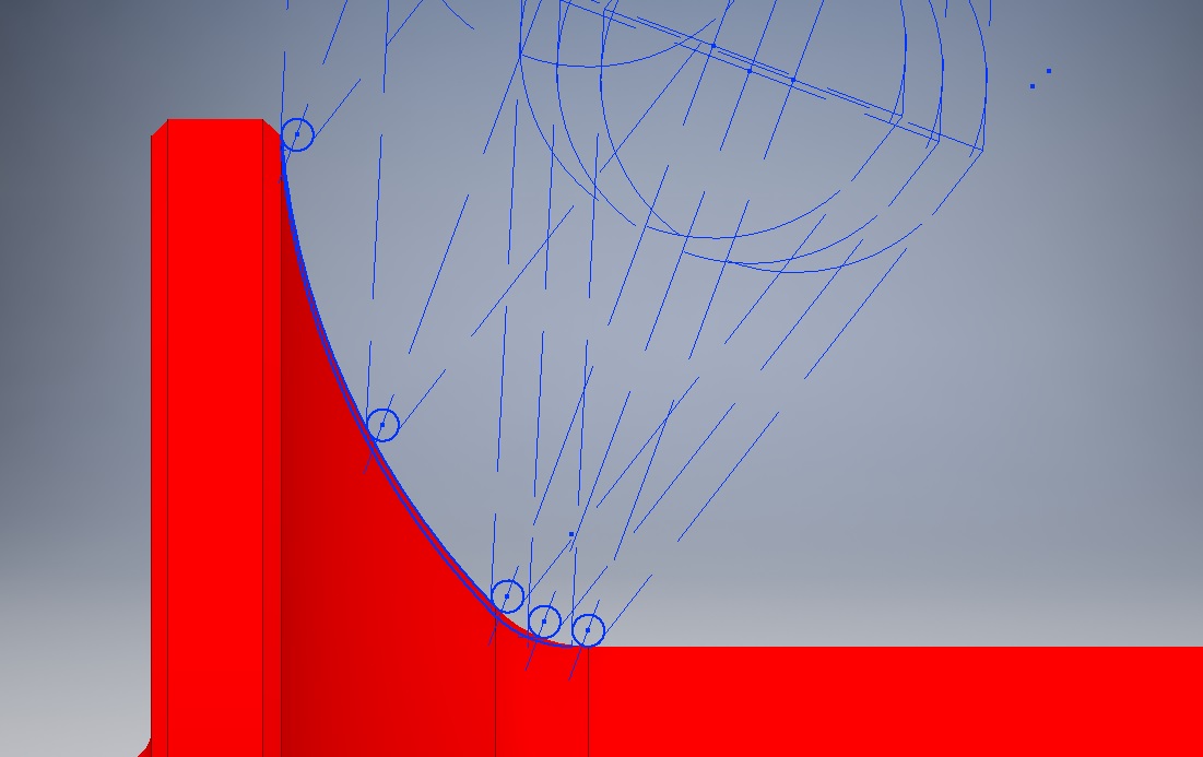
I am using Inventor CAD/CAM to generate g-code with a linuxcnc post processor. Not using control cutter compensation. Tooling is VNMG 331, material 316SS with coolant. Cutting speed is 300fpm and fpt is .005". Tool origin is tip tangent both x and z.
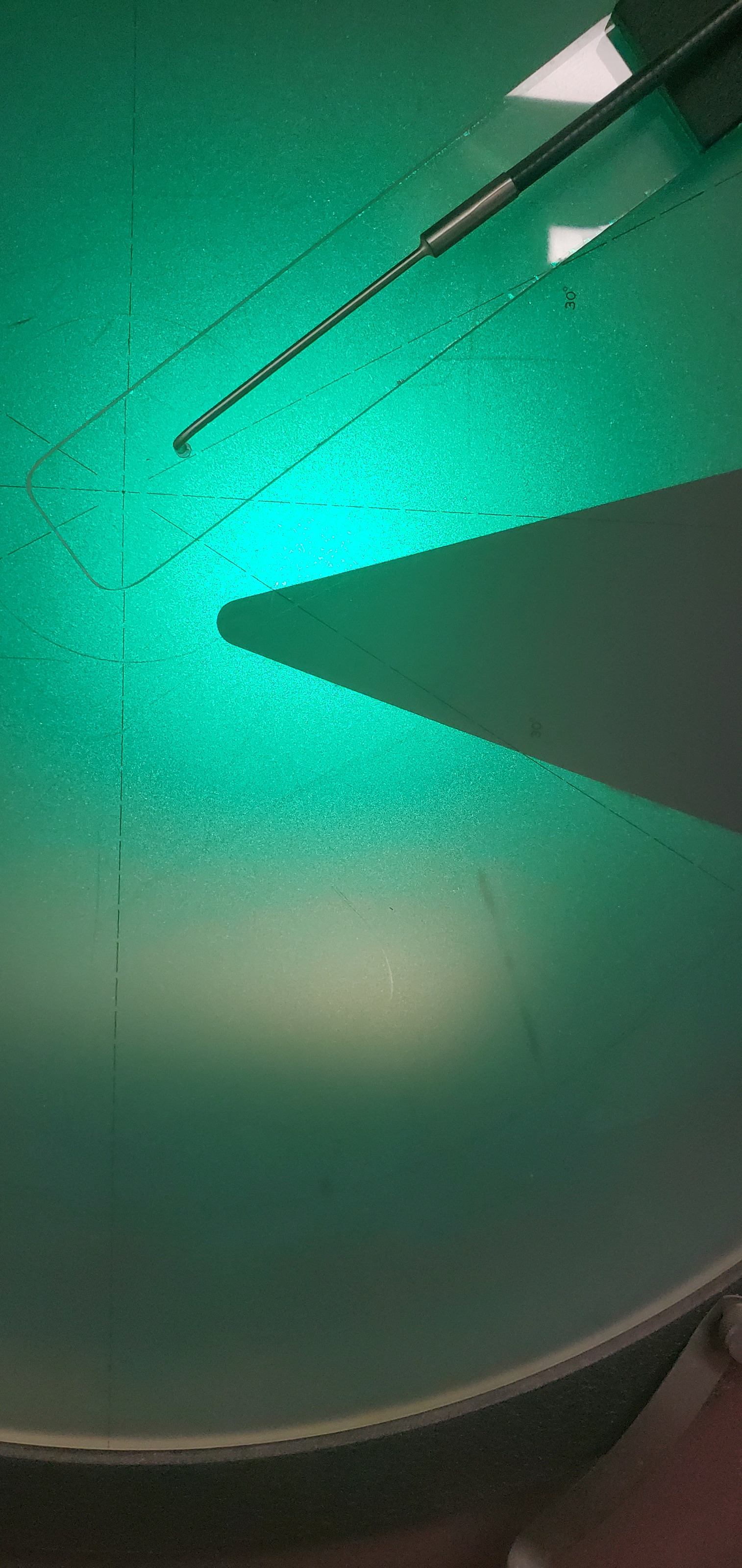
I verified that the G2 arc move on N66 should produce a .750" radius with a 1/64" tool radius by laying out in CAD. I am measuring the part radius with an optical comparator that has been calibrated against a radius gauge.My radius measurements have been all over the place from .720" to .740" with the optical comparator(measuring the same radius).
I am wondering if my arc profile is more like a series of line segments and the comparator gives me the best fit radius depending on the points I provide. Small deviations in point data result in large radius error?
Is there a trajectory planning setting that I haven't set correctly somewhere? Is +/-.005" tolerance on a radius a reasonable expectation?
Edit: I believe linuxcnc defaults to G64(Blend Without Tolerance Mode) by default. I will change to G61 and see if the radius dimension is improved. I did not understand how trajectory planning worked before posting.
If anyone on the forum has ideas that could help me out, I greatly appreciate it.
Thanks!