G71.1 and G70 issues in 2.9.2
- 42.1
- Offline
- New Member
-

Less
More
- Posts: 5
- Thank you received: 0
20 Mar 2024 22:17 #296415
by 42.1
G71.1 and G70 issues in 2.9.2 was created by 42.1
First post, pardon if it's in the wrong place. I've been beating my head against g71 for a while, finally got something workable but then G70 comes around to smack me back to reality ") I couldn't define my curve properly on a part in g71, it didn't like me setting the points, always got a "not monotonic" error, Finally worked that out by just using a more basic G2 command. It works great as a G71.1 file, it only becomes a problem when I try to finish it out with a G70, it then adds a cavity where before the arc cut off right where I wanted it to in G71.1. Below is the code, if you leave the G70 commented out it works as intended, but once the G70 is inserted, a nasty divot would be gouged out. Any help would be appreciated, really need to finish this part but G70 is not my friend
I couldn't define my curve properly on a part in g71, it didn't like me setting the points, always got a "not monotonic" error, Finally worked that out by just using a more basic G2 command. It works great as a G71.1 file, it only becomes a problem when I try to finish it out with a G70, it then adds a cavity where before the arc cut off right where I wanted it to in G71.1. Below is the code, if you leave the G70 commented out it works as intended, but once the G70 is inserted, a nasty divot would be gouged out. Any help would be appreciated, really need to finish this part but G70 is not my friend 
%
g00 g20 g40 g49 g90
g54 g18
g00 z2.5
x.375
o100SUB
G00 Z 2.5
X 0.25
G1 Z1.5 F300
g2 x.3750 z1.1768 r.1875
o100 ENDSUB
g71.1 Q100 x.375 z2.5 d.01 i.005 f100
//g70 Q100 x.375 z2.5 E0 D.005 f100
%
I couldn't define my curve properly on a part in g71, it didn't like me setting the points, always got a "not monotonic" error, Finally worked that out by just using a more basic G2 command. It works great as a G71.1 file, it only becomes a problem when I try to finish it out with a G70, it then adds a cavity where before the arc cut off right where I wanted it to in G71.1. Below is the code, if you leave the G70 commented out it works as intended, but once the G70 is inserted, a nasty divot would be gouged out. Any help would be appreciated, really need to finish this part but G70 is not my friend %
g00 g20 g40 g49 g90
g54 g18
g00 z2.5
x.375
o100SUB
G00 Z 2.5
X 0.25
G1 Z1.5 F300
g2 x.3750 z1.1768 r.1875
o100 ENDSUB
g71.1 Q100 x.375 z2.5 d.01 i.005 f100
//g70 Q100 x.375 z2.5 E0 D.005 f100
%
Please Log in or Create an account to join the conversation.
- Aciera
-

- Offline
- Administrator
-

Less
More
- Posts: 4731
- Thank you received: 2121
21 Mar 2024 10:12 #296449
by Aciera
Replied by Aciera on topic G71.1 and G70 issues in 2.9.2
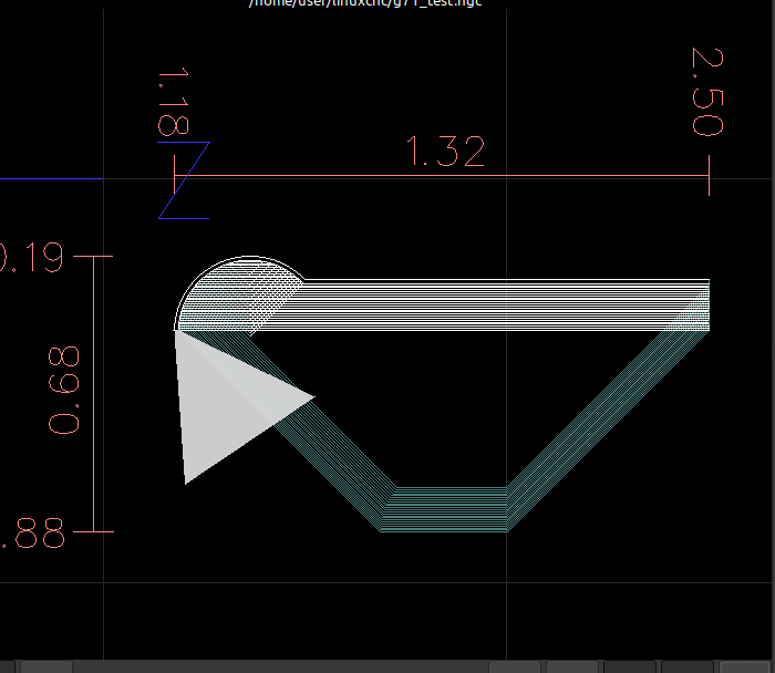
The reason G70 gives you a different path is because G71.1 does not cut pockets while G70 does. So in essence G70 actually cuts the path in the subroutine.
If you add a G71.2 to your program:
You can see the actual profile the subroutine creates.
If you add a G71.2 to your program:
%
g00 g20 g40 g49 g90

g54 g18

g00 z2.5
x.375

o100 SUB
G00 Z 2.5
X 0.25
G1 Z1.5 F300
g2 x.3750 z1.1768 r.1875
o100 ENDSUB

g71.1 Q100 x.375 z2.5 d.01 i.005 f100
g71.2 Q100 x.375 z2.5 d.01 i.005 f100
g70 Q100 x.375 z2.5 E0 D.005 f100

%
You can see the actual profile the subroutine creates.
Attachments:
Please Log in or Create an account to join the conversation.
- Aciera
-
- Offline
- Administrator
-
Less
More
- Posts: 4731
- Thank you received: 2121
21 Mar 2024 10:53 #296454
by Aciera
Replied by Aciera on topic G71.1 and G70 issues in 2.9.2
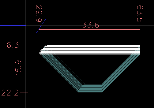
maybe try this:
would give you:
%
g00 g20 g40 g49 g90

g54 g18

g00 z2.5
x.375

o100 SUB
G00 Z 2.5
X 0.25
;G1 Z1.5 F300
G1 Z1.28 F300
g2 x.3750 z1.1768 r.1875
o100 ENDSUB

g71.1 Q100 x.375 z2.5 d.01 i.005 f100
g70 Q100 x.375 z2.5 E0 D.005 f100

%
would give you:
Attachments:
The following user(s) said Thank You: 42.1
Please Log in or Create an account to join the conversation.
- 42.1
- Offline
- New Member
-
Less
More
- Posts: 5
- Thank you received: 0
26 Mar 2024 21:29 #296842
by 42.1
Replied by 42.1 on topic G71.1 and G70 issues in 2.9.2
I tinkered around with this a bit, it runs as intended in the simulator nicely, thanks:) Would you be OK with explaining why the ; before the ;G1 Z1.5 line allows it all to work and also why the line below it (G1 Z1.28) is necessary? I tried tinkering with the numbers and haven't found the reason for Z1.28 to be effective, but I'm sure there is one. Any better methods for achieving the same result are welcome as well, it'll save me from asking more questions in the future I did OK with arcs and circles on the rare occasion I needed them milling, but I think I'm not looking at something correctly when using the lathe.
I did OK with arcs and circles on the rare occasion I needed them milling, but I think I'm not looking at something correctly when using the lathe. Please Log in or Create an account to join the conversation.
- Aciera
-
- Offline
- Administrator
-
Less
More
- Posts: 4731
- Thank you received: 2121
27 Mar 2024 08:24 - 27 Mar 2024 08:26 #296875
by Aciera
Replied by Aciera on topic G71.1 and G70 issues in 2.9.2
A semicolon ; tells the interpreter to ignore everything after it on that line (ie its a comment)
So if you delete this line there will be no change in the toolpath at all. I only left that in so you can still see the original line of code.
As for the arc move:
You're telling the controller to find a counter clock wise arc with radius (r.1875) from point (X 0.25 Z1.5), which is the endpoint of your G1 move, to point (x.3750 z1.1768), which is the endpoint of your G2 move. The only way to do this is the arc you see in your original post that cuts a pocket. If you want to avoid cutting a pocket with an arc of the given radius you need to move the endpoint of your G1 move closer to the end point of the arc.
The point I chose (X 0.25 Z1.28) is the other intersection of your G1 move with the arc of your original code since I thought that the geometry might be important to you, but other points are also possible of course. Often we would want the arc to be tangential on the final geometry.
This comes down to how Gcode works, no matter whether it's on a lathe or a mill.
linuxcnc.org/docs/html/gcode/g-code.html
Last edit: 27 Mar 2024 08:26 by Aciera.
The following user(s) said Thank You: tommylight, 42.1
Please Log in or Create an account to join the conversation.
- 42.1
- Offline
- New Member
-
Less
More
- Posts: 5
- Thank you received: 0
29 Mar 2024 18:52 - 29 Mar 2024 19:37 #297131
by 42.1
Replied by 42.1 on topic G71.1 and G70 issues in 2.9.2
Thank you I've always used // to comment out code lines, I didn't realize ; had that function. Seems like there was another one I used early on, lots of options. The 1" long skinny section was the critical dimension, the curve out is just reinforcement and a place to lay the user's thumb, it's a basic low-pressure wire insertion tool. The only thing I can't quite get a handle on is the precise locating of the 1.28 dimension. In my drawing, the arc ends at 1.3232, so I'm not quite clear on arc placement in this application. I'll see if I can upload a pic that shows my drawing, I'm guessing LINUXCNC sees the arc a little differently because that number won't work. I know I'm not looking at placement correctly from the software viewpoint because of that divot, just not sure where my error is. Since most of my use cases will involve starting and ending arcs from a line, I'm hoping for that "aha" statement I've tried a number of ways to work this out on my own, just not seeing my error.
I've always used // to comment out code lines, I didn't realize ; had that function. Seems like there was another one I used early on, lots of options. The 1" long skinny section was the critical dimension, the curve out is just reinforcement and a place to lay the user's thumb, it's a basic low-pressure wire insertion tool. The only thing I can't quite get a handle on is the precise locating of the 1.28 dimension. In my drawing, the arc ends at 1.3232, so I'm not quite clear on arc placement in this application. I'll see if I can upload a pic that shows my drawing, I'm guessing LINUXCNC sees the arc a little differently because that number won't work. I know I'm not looking at placement correctly from the software viewpoint because of that divot, just not sure where my error is. Since most of my use cases will involve starting and ending arcs from a line, I'm hoping for that "aha" statement I've tried a number of ways to work this out on my own, just not seeing my error.
Last edit: 29 Mar 2024 19:37 by 42.1.
Please Log in or Create an account to join the conversation.
Time to create page: 0.285 seconds