Stuck with spindle interface 7i76 card and weird BLDC driver
- timo
- Offline
- Elite Member
-

Less
More
- Posts: 174
- Thank you received: 50
05 Feb 2025 13:30 - 05 Feb 2025 13:33 #320741
by timo
Replied by timo on topic Stuck with spindle interface 7i76 card and weird BLDC driver
The spindle basically works now. But... when Linux CNC is not running, the spindle ramps often up to full speed. (I hooked the Enable pin of the drive to a +5V pin of the TB3, so obviously the PWM pin must put out full voltage when the software is not running yet)
What should be the output of the pwmgen, when no linux CNC is running?
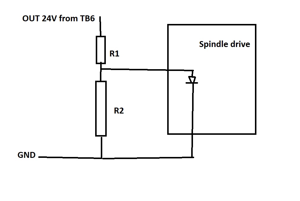
I think I could circumvent this by connecting one output of TB6 to the Input of the Spindle drive.
Problem: Output is set up for 24 V and I have no idea if that will damage the Spindle drive.
Is it a usual approach to just put resistors into the wiring?
Should it be even O.K. to just install one Resistor (R1) in the output line and cancel R2 altogether?
Attachments:
Last edit: 05 Feb 2025 13:33 by timo.
Please Log in or Create an account to join the conversation.
- PCW
-

- Away
- Moderator
-

Less
More
- Posts: 17625
- Thank you received: 5157
05 Feb 2025 16:07 - 05 Feb 2025 16:15 #320761
by PCW
Replied by PCW on topic Stuck with spindle interface 7i76 card and weird BLDC driver
Another way to fix that is to chose the output polarity of the PWM
so its 0V at startup or watchdog bite (the STEP- pin) and then invert
the PWM in the hal file.
Its still a good idea to disable the spindle when LinuxCNC is not running
If the enable is an optocoupler input, a single resistor (R1) will do
If its a 5V logic input, you need R2.
Safest would be to implement both (0 PWM at startup which is just a
wiring and hal change) and drive enable.
Last edit: 05 Feb 2025 16:15 by PCW.
The following user(s) said Thank You: timo
Please Log in or Create an account to join the conversation.
Time to create page: 0.407 seconds

