MESA 7i97 - connection of DC Tach-Motors (2)
- Hartwig
- Offline
- Junior Member
-

Less
More
- Posts: 22
- Thank you received: 2
15 Aug 2025 18:16 #333476
by Hartwig
MESA 7i97 - connection of DC Tach-Motors (2) was created by Hartwig
Dear members,
my milling machine has four 12 VDC Tacho-motors for the axes The direction change is done by a switch and by relais. It is not a CNC control, it is a distance-control managed by a Heidenhain TNC113 for each axis seperately only in sequence - not in parallel. So it is easy to change the motor running direction by a switch or by a relais. The motor amplifier accepts as external signals only 0 to 10 VDC and an "Enable".
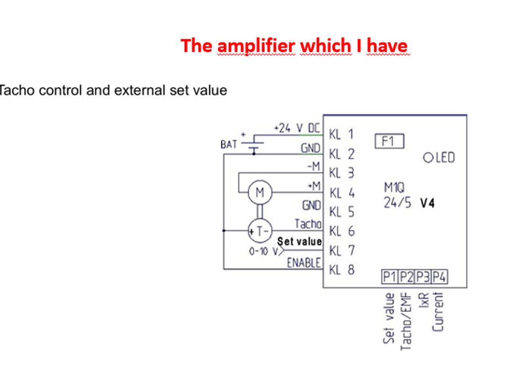
The question is how to handle the MESA output which ranges from -10VDC to + 10 VDC to have the motors run-direction changed.
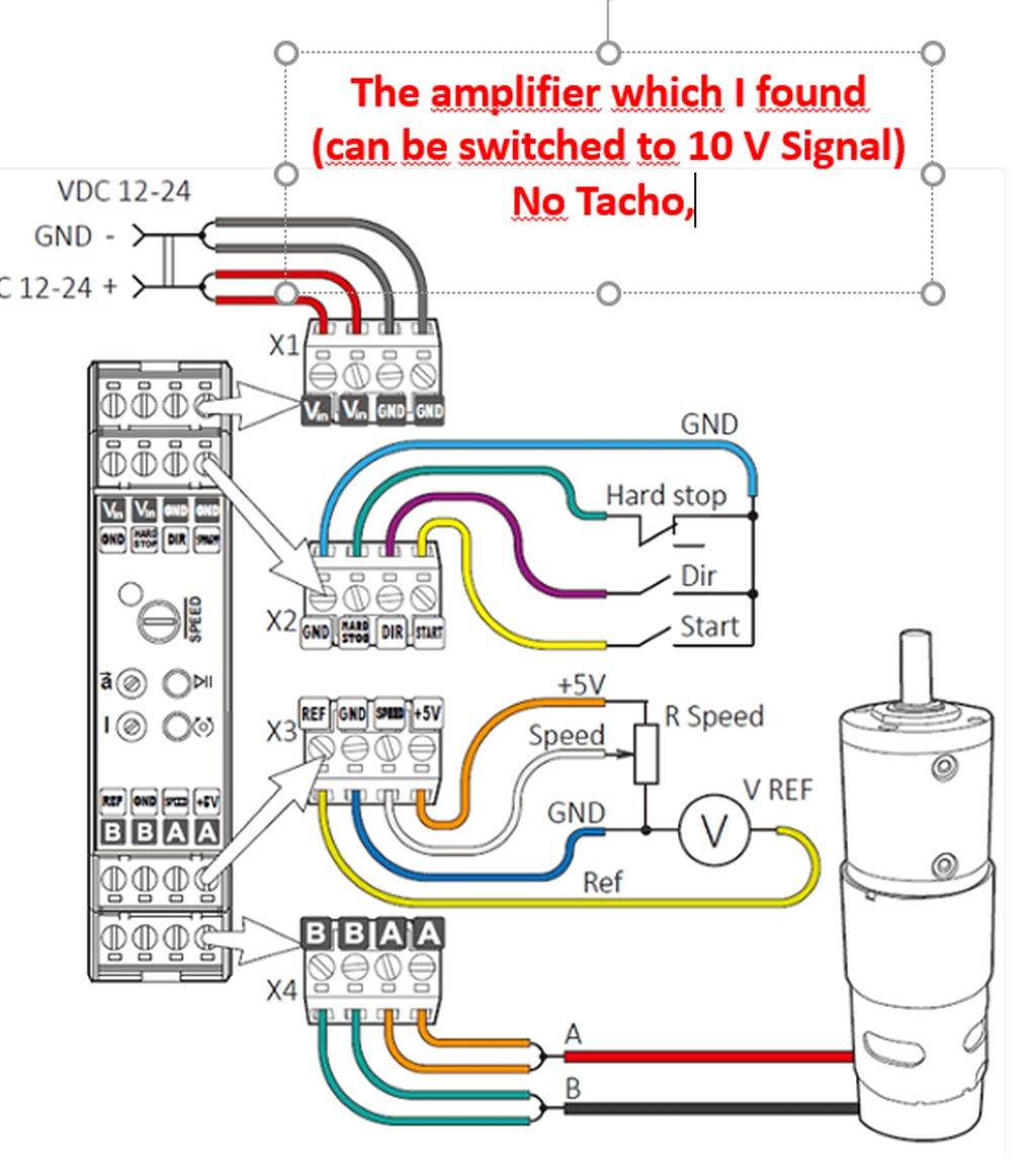
The only other option of aan amplifier which I found is from RS Components, which has a direction switch. But it works also only with a signal voltage of 0 to 10 VDC.
I there any helpfull idea how to realise the controls without relais?
Thanks a lot and best regards
Hartwig
my milling machine has four 12 VDC Tacho-motors for the axes The direction change is done by a switch and by relais. It is not a CNC control, it is a distance-control managed by a Heidenhain TNC113 for each axis seperately only in sequence - not in parallel. So it is easy to change the motor running direction by a switch or by a relais. The motor amplifier accepts as external signals only 0 to 10 VDC and an "Enable".
The question is how to handle the MESA output which ranges from -10VDC to + 10 VDC to have the motors run-direction changed.
The only other option of aan amplifier which I found is from RS Components, which has a direction switch. But it works also only with a signal voltage of 0 to 10 VDC.
I there any helpfull idea how to realise the controls without relais?
Thanks a lot and best regards
Hartwig
Attachments:
Please Log in or Create an account to join the conversation.
- PCW
-

- Away
- Moderator
-

Less
More
- Posts: 17945
- Thank you received: 5256
15 Aug 2025 18:24 - 15 Aug 2025 18:27 #333477
by PCW
Replied by PCW on topic MESA 7i97 - connection of DC Tach-Motors (2)
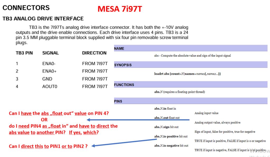
You could run a unipolar analog drive (0 to +10V) with direction control by using the
abs component on the output of the position PID loop in LinuxCNC. The abs component
has a sign output that could be used for direction control.
abs component on the output of the position PID loop in LinuxCNC. The abs component
has a sign output that could be used for direction control.
Last edit: 15 Aug 2025 18:27 by PCW.
Please Log in or Create an account to join the conversation.
- Hartwig
- Offline
- Junior Member
-
Less
More
- Posts: 22
- Thank you received: 2
17 Aug 2025 12:14 #333540
by Hartwig
Replied by Hartwig on topic MESA 7i97 - connection of DC Tach-Motors (2)
Thanks a lot for the answer.
Good message: it is doable and I can use the RS Pro amplifier. Unfortunately the Mattke not. In any case, I have to forget the Tach function of the motors.
Sorry for my further questions - I`m an absolute beginner and not an experienced programmer. This are my first steps in learning to run.
Below I have formulated my questions in red font. I need to understand, whether the I/Os on my MESA are sufficient by number and by functionality.
Thanks a lot and best regards
Hartwig
Attachments:
Please Log in or Create an account to join the conversation.
- PCW
-
- Away
- Moderator
-
Less
More
- Posts: 17945
- Thank you received: 5256
17 Aug 2025 14:07 #333546
by PCW
Replied by PCW on topic MESA 7i97 - connection of DC Tach-Motors (2)
Very briefly:
In the hal file (use the sample: basic7i97 or use MesaCT to generate the basic configurations)
The PID output pin connects to the PWM value pin. You would change this connection to
add the abs component so you have:
PID output --> abs in --> abs out --> PWM value
That is, for example, in the basic7i97 hal file you have:
net x-output => [HMOT](CARD0).pwmgen.00.value
This would need to change to:
net x-output => abs.0.in
net abs-x-output <= abs.0.out
net abs-x-output => [HMOT](CARD0).pwmgen.00.value
The following user(s) said Thank You: Hartwig
Please Log in or Create an account to join the conversation.
Time to create page: 0.389 seconds