7i96s Pinout/Wiring Help
- maruf1777
- Offline
- New Member
-

Less
More
- Posts: 11
- Thank you received: 0
30 Oct 2025 18:39 #337505
by maruf1777
7i96s Pinout/Wiring Help was created by maruf1777
Hello everyone
I am encountering an issue that appears to be EMI-related despite applying the usual mitigation steps.
EMI / System Setup:
VFD in steel enclosure
Input EMI filter
Ferrite rings on VFD output and all related cables
Shielded spindle/motor cables (grounded both ends)
AC/VFD cabling physically separated from DC lines
High-current DC cables are shielded and routed separately
Control Setup:
I am using the 7i96S encoder pins for MPG inputs (I have no motor or spindle encoders).
I do not have any unused OUT pins and only 4 available IN pins.
To get X, Y, Z, X1, X10, and X100 signals, I wired them to Raspberry Pi GPIO using external 10k pull-ups.
Issue
After wiring the MPG inputs, some of the pins intermittently remain latched HIGH or LOW, making jog selection unreliable. This problem has occurred twice, and both times it started after spindle-speed testing.
Earlier in setup, I believe I damaged one of the 7i96S step/dir channels. After that, instead of wiring STEP- and DIR- to GND and STEP+ / DIR+ to the respective inputs, I reversed them — STEP+ and DIR+ to +5V and STEP- / DIR- to the Mesa pins.I have since added additional ferrites and shielding, Ferrites on servo lines, data cables, and MPG cable
Steel mesh added to enclosure ventilation fans but the issue persists.
I am now planning to use the P1 pins on the 7i96S for X/Y/Z and X1/X10/X100 inputs instead.
W6 jumper is OFF.
Questions
- The MPG has extra wires that appear intended to power LEDs or similar features. Can these be safely powered from the 5V rail, or is that risky for the inputs?
- Where exactly are pin 1 and pin 2 physically located on the P1 expansion header?
- Which P1 pins are appropriate to use for these MPG signals?
- May I safely use 5V for the MPG input power in this configuration?
- Any recommendations to avoid EMI issues when using these inputs on the 7i96S?
Thank you for your help.
Attachments:
Please Log in or Create an account to join the conversation.
- PCW
-

- Offline
- Moderator
-

Less
More
- Posts: 17992
- Thank you received: 5281
30 Oct 2025 19:11 #337508
by PCW
Replied by PCW on topic 7i96s Pinout/Wiring Help
1. No 7I96S step/dir pin should ever be wired to 5V or ground.
This directly shorts out the drivers and if done for more
than a short time will damage the driver chips.
2. Not sure what you mean by this:
I wired them to Raspberry Pi GPIO using external 10k pull-ups.
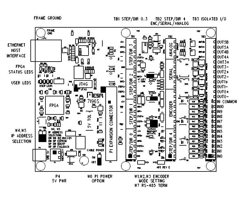
3. Are the pins you have trouble with encoder pins (TB2 pins)
or isolated input pins?
P1 pinout is standard header pinout
pin one is marked with the Square
1 2
3 4
5 6
7 8
etc
Note that mesaflash show equivalent DB25 pins
(if you use the latest mesaflash you can show HDR26 pins
with the --dbname hdr26 option)
This directly shorts out the drivers and if done for more
than a short time will damage the driver chips.
2. Not sure what you mean by this:
I wired them to Raspberry Pi GPIO using external 10k pull-ups.
3. Are the pins you have trouble with encoder pins (TB2 pins)
or isolated input pins?
P1 pinout is standard header pinout
pin one is marked with the Square
1 2
3 4
5 6
7 8
etc
Note that mesaflash show equivalent DB25 pins
(if you use the latest mesaflash you can show HDR26 pins
with the --dbname hdr26 option)
Please Log in or Create an account to join the conversation.
- unknown
- Offline
- Platinum Member
-

Less
More
- Posts: 888
- Thank you received: 325
30 Oct 2025 19:26 #337512
by unknown
Replied by unknown on topic 7i96s Pinout/Wiring Help
If you are using the DIR+ and STEP+ do not connect the DIR- nor the STEP- to ground. When using the - signals do not connect the + to 5v.
When I installed my VFD the wiring diagram included an AC line reactor, which I duly installed.
Generally the shielding is only connected at one end, this is to prevent ground loops.
Personally I wouldn't supply any voltage than 3.3v to the input of an RPi. If 5v signal was required I would either using a 74lvc245 or an opto isolator, with the opto isolator being the preferred choice, and despite what some schematics suggest do not connect the grounds and do use seperate power sources for each side of the opto, otherwise you are not getting any isolation.
Any grounds should be connected to a single point, aka star, once again to prevent ground loops.
Make sure to use quality power supplies, Meanwell from a reliable supplier, are a good choice.
Simple things such as using bootlace ferrules is good practice instead of bare wires into screw terminals. When using crimp connectors do not solder the joint, the solder will which up the wire and any movement will cause the wire to break. A proper crimp will cold weld the wire and crimp connector. This is the same thing that happens when wire wrapping, ask NASA about the effectiveness of a quality wire wrapped connection .
Please Log in or Create an account to join the conversation.
Time to create page: 0.324 seconds