
Lathe C axis homing
- jetbadger
- Offline
- New Member
-

- Posts: 19
- Thank you received: 2
The drive is at 10000 PPR and around 1.45:1 spindle:motor overdrive, from my calculations 6k rpm spindle speed is around the limit. there is a 2500 step/10k line encoder on the spindle itself I use for feedback.
I am looking through the HAL again and wondering maybe I DO have the scaling wrong? Though the positions and speeds report correct, maybe the scales are backwards, the end math turns out correct, but calculations midway are off? I'm trying to think of anything now, really.
- -ENCODER_SCALE is 10000
- -Spindle SCALE is 114.83 (10000/1.45/60) (not sure why it needs to be divided by 60 though? I assume because RPS instead of RPM, but I thought this value should not be bound by time, only steps/rev? I'm not sure...
- -JOINT_2 (C axis in my case) SCALE is 19.07 (10000/1.45/360). I turned on the scale switching in M102/103, not sure how you get it to work without that?
Please Log in or Create an account to join the conversation.
- spumco
- Offline
- Platinum Member
-

- Posts: 2180
- Thank you received: 905
First, it helped me to stop thinking of INI file terms like ENCODER_SCALE whenever they are used to set the value of something in HAL. Think about the underlying pins when working on the math, not the arbitrary INI parameter name. I got confused (still do) between all the various 'NNN_SCALE' things in INI and would mix up what was affecting what. Helps when you write them out all in one place:
- encoder.N.scale = [SPINDLE_N] ENCODER_SCALE = 10000
- stepgen.N.position-scale = yada yada yada
So hurdle #1 - spindle and c-axis are in different units. Spindle is in revolutions, c-axis is in degrees. This causes brain hurt.
#2 - as you noticed, spindle scale is a velocity thing, so it's a RPM/RPS formula not steps per degree.
#3 - remember that my spindle drive is internally in velocity mode ONLY, and my stepgen is always in velocity-mode... so I don't switch the stepgen position-scale via M102/103.
If you are switching the drive internally, you will almost certainly need to change the stepgen scale for each drive mode.
Please Log in or Create an account to join the conversation.
- jetbadger
- Offline
- New Member
-
- Posts: 19
- Thank you received: 2
I'm still not wrapping my head fully around the velocity/position mode thing. It does make sense that if you have the drive in same scale and always in velocity mode both in stepgen and the drive that the scale shouldn't be crucial and the PID could take care of it, but having it the way I do which is stepgen in velocity and drive in step/dir position mode to me seems like should have to be the same thing, but it isn't for some reason.
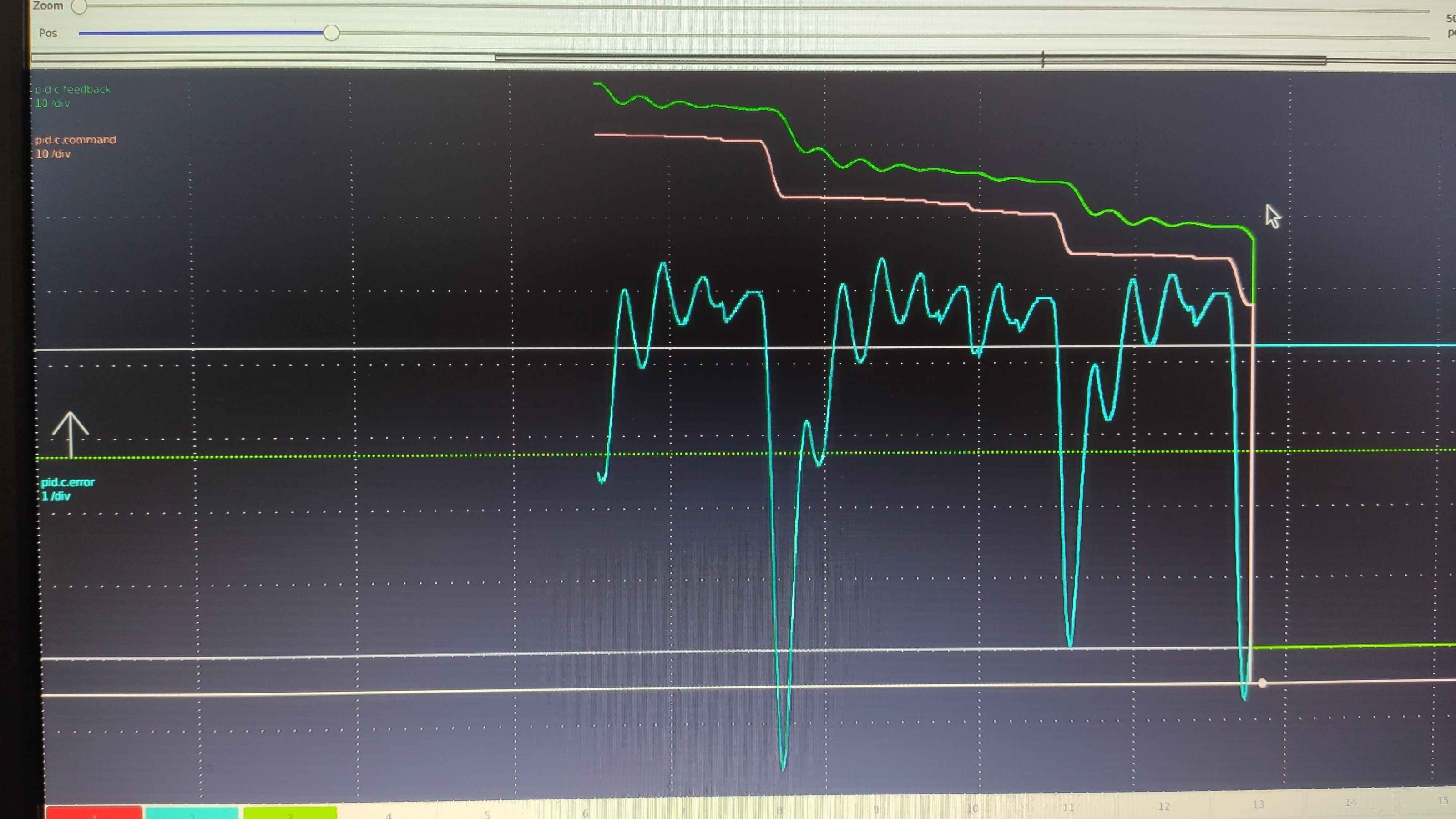
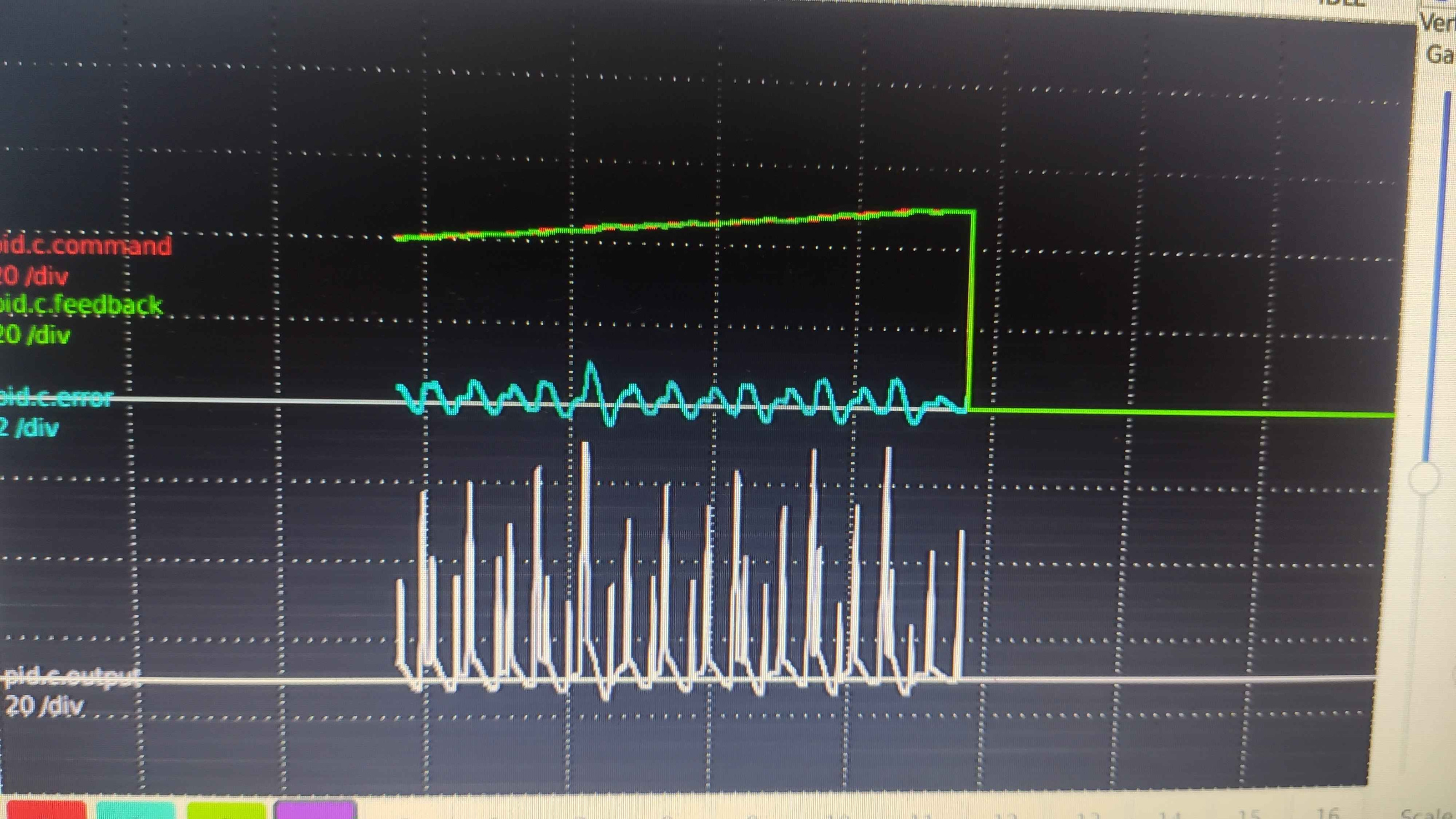
I've spent some time today on the schaublin and the C axis hurdle. Some new progress is that I think it all has to do with the PID ratios and acceleration. I played around with it watching the plots and in the end it got slightly better, but the commanded position is still progressing very slow.
I've looped back the stepgen position-fb instead of the encoder for everything and it's still the same as with encoder so I'm still baffled. In that setup it should be the same as X/Z axis but it's still acting drunk. Maybe I'll think of something else as I didn't spend too much time today on that, instead did some other functionality of the machine, which is more practice in hal and ladder so maybe one day it'll all just click

Please Log in or Create an account to join the conversation.
- spumco
- Offline
- Platinum Member
-
- Posts: 2180
- Thank you received: 905
In that setup it should be the same as X/Z axis but it's still acting drunk.
How is the servo connected to the spindle? My biggest problem a couple years ago when I started fiddling was that my spindle servo was WAY undersized for use as a direct-drive positioning motor.
I had a "2.2kw" BLDC servo connected through a 1.5:1 belt drive. Soon as I put a chuck on the 5C spindle the inertia ratio was so unfavorable the servo couldn't really handle precise positioning.
I now have a comparatively monsterous 3.7kw (actual rating, not inflated) motor connected to the same spindle through a 2.5:1 belt. Night and day difference. That motor can horse the spindle around like it's barely there.
Maybe you have a significant inertia mismatch? Don't want to throw you a red herring, but something to think about.
Please Log in or Create an account to join the conversation.
- jetbadger
- Offline
- New Member
-
- Posts: 19
- Thank you received: 2
The motor is rated 5.5kW. It's on the slower side but the torque should be plenty I'd think. I've spent the last night rolling around thinking of this and I'm pretty sure it must be something to do with step scaling, accel values or something like that. Maybe there is too many steps? 10k per revolution and it's causing issues for unknown (to me) reason. I will try to test that next and see if that makes any difference.
Please Log in or Create an account to join the conversation.
- PCW
-
- Offline
- Moderator
-

- Posts: 18109
- Thank you received: 5329
That would help diagnose the issue.
Please Log in or Create an account to join the conversation.
- jetbadger
- Offline
- New Member
-
- Posts: 19
- Thank you received: 2
Attachments:
Please Log in or Create an account to join the conversation.
- PCW
-
- Offline
- Moderator
-
- Posts: 18109
- Thank you received: 5329
Please Log in or Create an account to join the conversation.
- spumco
- Offline
- Platinum Member
-
- Posts: 2180
- Thank you received: 905
I finally checked your drive manual. Your drive can handle 4mhz pulse input when using differential signals.
If your drive is set to the default input of 10,000ppr (parameter P0.22), and you want ~4100rpm (motor) for 6000rpm (spindle), that means your maximum pulse frequency will be ~680khz.
Tuning or inertia issues aside, it also results in a fairly coarse positioning resolution of 19 pulses per degree.
You could increase the drive positioning resolution by a factor of 4 without running in to the drive's (or Mesa's) input frequency limit.
However...unless I'm looking at the wrong manual - or you have an unlisted motor - the 5.5kw servo is advertised as having a max speed of 2000rpm.
Do you have a different motor/drive than is listed in the manual? If not, I'm not sure that motor is going to do what you want in spindle mode.
Please Log in or Create an account to join the conversation.
- jetbadger
- Offline
- New Member
-
- Posts: 19
- Thank you received: 2
That's exactly the issue I can't get rid of. This is just with G0Cxx commands. I'm suspecting if I zoomed in the second plot enough it would look the same just at higher frequency. For example when homing it acts fine but that's probably because the commanded position is instantly much different and the PID loop takes care of reaching it. But here the commanded position supposed to trail ahead by some degree to let the PID do it's thing I suppose and it just doesn't seem to work with the joint either reaching the position and output going to 0 and then falling behind and shooting up, rinse and repeat... If I lower the P ratio to where it trails just behind, the commanded position slows down aswell eventually leading to coarse steps like before.I guess my question now would be: Why are there relatively huge steps in the commanded position?
I'm aware that the motor is not exactly right for this, however it was already on there before me. It's the same one from the manual with 1500rpm rated speed, making for a pretty slow spindle. The 4MHz value is what I had in mind when figuring out the pulse widths and so on, I admit though I forgot about the motor rating, but for now in spindle mode I only had it in the hundreds range and in axis mode it's even slower. I will try increasing the resolution and see, thanks.I finally checked your drive manual. Your drive can handle 4mhz pulse input when using differential signals.
If your drive is set to the default input of 10,000ppr (parameter P0.22), and you want ~4100rpm (motor) for 6000rpm (spindle), that means your maximum pulse frequency will be ~680khz.
Tuning or inertia issues aside, it also results in a fairly coarse positioning resolution of 19 pulses per degree.
You could increase the drive positioning resolution by a factor of 4 without running in to the drive's (or Mesa's) input frequency limit.
Please Log in or Create an account to join the conversation.