Rotary Axis
- SwitchWitch
- Offline
- Junior Member
-

Less
More
- Posts: 31
- Thank you received: 2
02 Jun 2026 19:05 #346860
by SwitchWitch
Rotary Axis was created by SwitchWitch
Looking for some community advice:
I’m planning to add a 4th axis (rotary A-axis) to my milling machine. In principle, that’s not a problem. What I’m wondering is how to best handle situations where the stock isn’t clamped perfectly centered in the chuck/vise.I think it’s unrealistic to expect the workpiece to be mounted absolutely concentric every single time.I’m using the Probe Basic interface. I checked the probing functions to see if I could probe and compensate with G52, but that doesn’t seem to be possible.
How would you approach this? Would you probe the offset somehow, use a different work coordinate system, or handle it another way?I’d appreciate any tips or suggestions!
Please Log in or Create an account to join the conversation.
- spumco
- Offline
- Platinum Member
-

Less
More
- Posts: 2126
- Thank you received: 882
02 Jun 2026 20:32 #346862
by spumco
Replied by spumco on topic Rotary Axis
I program (F360) using the center of rotation as Y0Z0.
Your example shows a self-centering vise, and I assume it'll be connected to the axis with a zero-point system. If your adapter plate is adjustable you can indicate the adapter & zero-point chuck in very close. From that point on the vise should self-center close enough.
For round parts (3-jaw chuck) treat it like a 'set-true' lathe chuck. Chuck up the part and indicate it concentric with the axis of rotation (dial test indicator). Loosen the chuck on the backplate and tap it around.
Once it's turning concentric the Probe Basic 'Ridge & Valley' probing routine (in Y) will find Y-axis center. Once you have Y-center, probe in Z and then adjust Z-offset based on stock diameter.
As far as probing the center of rotation for a prismatic part - assuming you've adjusted your vise & zero-point to be on center...
The above headache of indicating is why I switched to encoder index homing on my A-axis, and am in the process of doing the same thing on my XYZ axes.
Your example shows a self-centering vise, and I assume it'll be connected to the axis with a zero-point system. If your adapter plate is adjustable you can indicate the adapter & zero-point chuck in very close. From that point on the vise should self-center close enough.
For round parts (3-jaw chuck) treat it like a 'set-true' lathe chuck. Chuck up the part and indicate it concentric with the axis of rotation (dial test indicator). Loosen the chuck on the backplate and tap it around.
Once it's turning concentric the Probe Basic 'Ridge & Valley' probing routine (in Y) will find Y-axis center. Once you have Y-center, probe in Z and then adjust Z-offset based on stock diameter.
As far as probing the center of rotation for a prismatic part - assuming you've adjusted your vise & zero-point to be on center...
- Z-axis
- clamp a piece of stock in the self-centering vise
- Skim cut one side using Y-axis to establish a flat plane - doesn't need to be a huge area
- Rotate 180
- Skim cut opposite side at the same Z-position - preferably without changing Z-position between cuts
- Measure part thickness (and checking for taper to ensure 180 degrees is actually 180!)
- Probe part in Z, setting Z0 to top of part (probably automatic in probing routine)
- Adjust Z-offset by half the measured thickness. Z0 should now be center of rotation
- Y-axis
- Probe your vise on one side (jaws horizontal)
- Rotate vise 180
- Probe same vise surface again, approach from the opposite Y-direction
- Difference between these two is the Y-axis center.
- From that point use a scale, calipers or a jig to center the stock in the vise along the jaws.
- Bonus
- Write down the machine coordinates once you've found center of rotation in Y and Z
- Next time you home the machine, repeat the above indicating and compare the numbers. Any difference is the error window for your machine's homing position.
- Double-bonus
- Avoid removing your 4th axis at all costs so you don't have to re-indicate

- Avoid removing your 4th axis at all costs so you don't have to re-indicate
The above headache of indicating is why I switched to encoder index homing on my A-axis, and am in the process of doing the same thing on my XYZ axes.
Please Log in or Create an account to join the conversation.
- djdelorie
- Away
- Senior Member
-

Less
More
- Posts: 78
- Thank you received: 15
02 Jun 2026 21:58 #346864
by djdelorie
Replied by djdelorie on topic Rotary Axis
It sounds like you either need to (1) make your stock a little bigger and *mill* it true after mounting, or (2) probe the part and update your origin in CAM. It would be cool if there were a kinematics layer that could do the G52 equivalent in a rotating frame.
If you're doing a production run, could you put in the equivalent of a vice stop on your chuck, so that every part is at least in the *same* place?
If you're doing a production run, could you put in the equivalent of a vice stop on your chuck, so that every part is at least in the *same* place?
Please Log in or Create an account to join the conversation.
- SwitchWitch
- Offline
- Junior Member
-
Less
More
- Posts: 31
- Thank you received: 2
03 Jun 2026 10:26 #346870
by SwitchWitch
Replied by SwitchWitch on topic Rotary Axis
Thanks for the detailed writeup — very helpful, especially the encoder index homing tip (I use A6 Servos with absolute encoders myself)!
For the daily workflow with changing stock I would like to find an easier way to avoid the manual indicating and skim cuts: a small probing macro that finds the rotary center automatically and sets G52.
The idea:
1. Clamp the stock (no need to center it carefully)
2. Run the macro — it probes at A=0° and A=180° in Y, calculates the midpoint, and sets G52 Y to the center of rotation
3. Swap to the cutting tool and run the program
With the WCS origin set to the rotary axis in CAM (Y0 = center of rotation), one single setup covers all rotation angles. No skim cuts, no calipers, no manual offset math — roughly 30 seconds per part.
G52 persists across resets in LinuxCNC by default, so the machine-level calibration (the fixed offset between G54 and the rotary axis) only needs to be done once after homing. The macro then corrects only for the actual clamping offset of each individual part.
What do you think?
Might be worth adding something like this to the ProbeBasic probing tab — the Rotary Axis tab seems like the natural home for it.
Please Log in or Create an account to join the conversation.
- spumco
- Offline
- Platinum Member
-
Less
More
- Posts: 2126
- Thank you received: 882
03 Jun 2026 14:13 #346872
by spumco
Replied by spumco on topic Rotary Axis
I've attached an A-axis probing routine - it's from PathPilot. I think it's suitable for cylindrical stock along A, not really for prismatic stock.
I've not tested it, but it'd probably be a good starting point for someone to test/tweak and then submit to the ProbeBasic devs for inclusion in PB mainline.
2. Run the macro — it probes at A=0° and A=180° in Y, calculates the midpoint, and sets G52 Y to the center of rotation
For this to work the following must be true:
If you have TCP that takes care of everything.
If you adjust CAM after probing, that also takes care of everything.
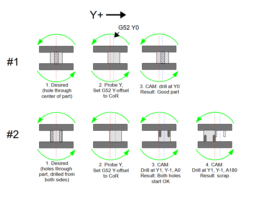
But just probing and shifting Y will result in bad parts unless you're only machining at one A-position.
I didn't draw the other problem... but not only will features not line up, the part will orbit the actual CoR, which means at A90/A-90 the Z-position will be higher/lower than CAM expects it to be. Maybe crashy-crashy.
The only reason to probe is if you're doing 2nd op parts and have to line up features with existing surfaces. Even then you'll probe, adjust CAM (or TCP), and pray.
No skim cuts, no calipers, no manual offset math — roughly 30 seconds per part.
Or use a work stop that gets the stock centered enough to take care of a little excess material - roughly 1 second per part.
I've not tested it, but it'd probably be a good starting point for someone to test/tweak and then submit to the ProbeBasic devs for inclusion in PB mainline.
2. Run the macro — it probes at A=0° and A=180° in Y, calculates the midpoint, and sets G52 Y to the center of rotation
For this to work the following must be true:
- You have some sort of TCP enabled, or
- You adjust rotational point to stock offset in CAM after probing, or
- You have very simple parts, with very simple programs, and
- an internal macro/subroutine 'adjusts' the Z/Y positions for every single point in the program based on the probed offset.
If you have TCP that takes care of everything.
If you adjust CAM after probing, that also takes care of everything.
But just probing and shifting Y will result in bad parts unless you're only machining at one A-position.
I didn't draw the other problem... but not only will features not line up, the part will orbit the actual CoR, which means at A90/A-90 the Z-position will be higher/lower than CAM expects it to be. Maybe crashy-crashy.
The only reason to probe is if you're doing 2nd op parts and have to line up features with existing surfaces. Even then you'll probe, adjust CAM (or TCP), and pray.
No skim cuts, no calipers, no manual offset math — roughly 30 seconds per part.
Or use a work stop that gets the stock centered enough to take care of a little excess material - roughly 1 second per part.
The following user(s) said Thank You: tommylight
Please Log in or Create an account to join the conversation.
- SwitchWitch
- Offline
- Junior Member
-
Less
More
- Posts: 31
- Thank you received: 2
04 Jun 2026 15:58 #346899
by SwitchWitch
Replied by SwitchWitch on topic Rotary Axis
Thanks so much for the detailed response and the PathPilot macro — really appreciated!
You're absolutely right that blindly setting G52 Y without accounting for Z would cause the orbit problem you described. That's an important warning and worth highlighting.
The key assumption I should have stated more clearly upfront: the CAM origin must be placed on the rotary axis itself — not on the stock surface. With Z0 and Y0 both sitting on the center of rotation in CAM, the G52 Y correction only compensates for the actual clamping offset of the stock, and the orbit problem doesn't arise. The part isn't referencing a point on the stock that moves with it — it's referencing the fixed axis center.
With that setup in place, I think TCP isn't needed either — Fusion pre-computes all positions for a table-type A-axis, so the controller just executes straight X/Y/Z/A moves.
Thanks again for pushing back on this — it forced a much clearer explanation of the preconditions.
Please Log in or Create an account to join the conversation.
- spumco
- Offline
- Platinum Member
-
Less
More
- Posts: 2126
- Thank you received: 882
04 Jun 2026 17:01 #346902
by spumco
Replied by spumco on topic Rotary Axis
With Z0 and Y0 both sitting on the center of rotation in CAM, the G52 Y correction only compensates for the actual clamping offset of the stock, and the orbit problem doesn't arise. The part isn't referencing a point on the stock that moves with it — it's referencing the fixed axis center.
I still fail to understand the point of probing and using an offset. What exactly are you offsetting?
If you position the part mostly in-line with the actual CoR and program a bit of extra stock in CAM, you will never need to probe and you will never plow in to unexpected material.
I still fail to understand the point of probing and using an offset. What exactly are you offsetting?
- If the actual CoR position is not known and you probe the part - you don't know how far to offset.
- If the actual CoR position is known and you probe the part, you know how much to offset, but
- the CAM doesn't know how far you've offset, so features will be machined in relation to the CoR, but not to the stock position
- In the case of a profile-type toolpath - depending on how far offset the stock is from actual CoR - you will need extra material on one side and risk taking an extra-heavy cut on the other
If you position the part mostly in-line with the actual CoR and program a bit of extra stock in CAM, you will never need to probe and you will never plow in to unexpected material.
Please Log in or Create an account to join the conversation.
Time to create page: 0.152 seconds