
Shift-rotary XY kinematics
- tuxcnc
- Away
- Elite Member
-

Less
More
- Posts: 311
- Thank you received: 60
19 Nov 2026 14:54 #350846
by tuxcnc
Shift-rotary XY kinematics was created by tuxcnc
I would like to build a simple hot-wire foam-cutting machine.
I already have one with a conventional configuration, but I need something truly small yet precise. It will be used to create sacrificial patterns for metal casting. Since I am unable to melt large quantities of metal, a working area slightly larger than 100x100x100 mm will be more than sufficient.
I’ve come up with a very simple and compact design consisting of a linear axis (ready-made slider from AliExpress) and a rotary axis (stepper motor with built-in gear reduction). Unfortunately, when I search on Google, I only find "polar" kinematics, but that’s not what this is.
In polar kinematics, you have a rotating radius of variable length; in my design, the radius is fixed, but the pivot point itself shifts.
I’ve created a simple drawing that should make it easy to understand.
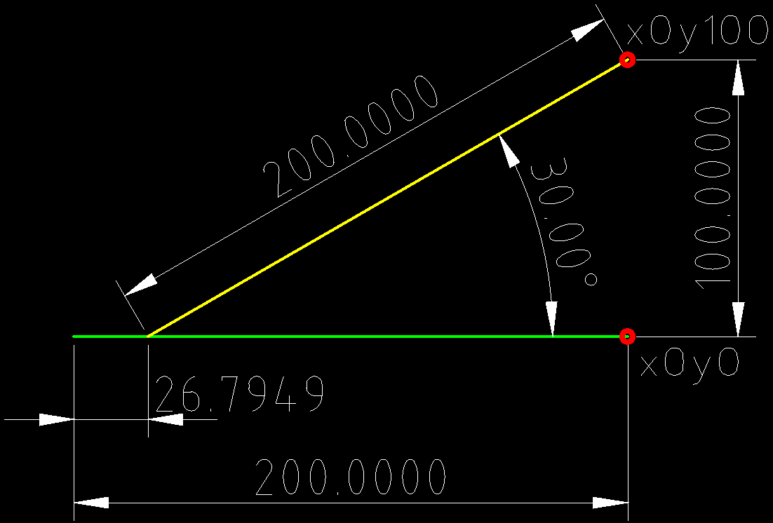
The yellow and green lines represent the same arm—the different colors are just for better visibility. The red color represents the tool. The dimensions correspond to the machine I intend to build.
The green line shows the arm in a horizontal position, set so that the tool is at the (0,0) coordinate.
To move the tool to the (0,100) coordinate, the arm must be rotated by 30 degrees, and the pivot point must be shifted along the X-axis by approximately 26.8 mm.
This is elementary-level geometry, and I have no trouble understanding the calculations involved (using the sine and cosine of the rotation angle).
My problem is that I have never written a kinematics module for LinuxCNC, and I’m not quite sure how to go about it. So, rather than struggling through trial and error, I decided to ask if anyone has already done this, if there’s an off-the-shelf solution available, or if someone with experience in other types of kinematics could put this together in a matter of minutes.
The HAL component only needs to expose one user-facing pin: the arm length. The rest is just a matter of applying the appropriate formulas.
I already have one with a conventional configuration, but I need something truly small yet precise. It will be used to create sacrificial patterns for metal casting. Since I am unable to melt large quantities of metal, a working area slightly larger than 100x100x100 mm will be more than sufficient.
I’ve come up with a very simple and compact design consisting of a linear axis (ready-made slider from AliExpress) and a rotary axis (stepper motor with built-in gear reduction). Unfortunately, when I search on Google, I only find "polar" kinematics, but that’s not what this is.
In polar kinematics, you have a rotating radius of variable length; in my design, the radius is fixed, but the pivot point itself shifts.
I’ve created a simple drawing that should make it easy to understand.
The yellow and green lines represent the same arm—the different colors are just for better visibility. The red color represents the tool. The dimensions correspond to the machine I intend to build.
The green line shows the arm in a horizontal position, set so that the tool is at the (0,0) coordinate.
To move the tool to the (0,100) coordinate, the arm must be rotated by 30 degrees, and the pivot point must be shifted along the X-axis by approximately 26.8 mm.
This is elementary-level geometry, and I have no trouble understanding the calculations involved (using the sine and cosine of the rotation angle).
My problem is that I have never written a kinematics module for LinuxCNC, and I’m not quite sure how to go about it. So, rather than struggling through trial and error, I decided to ask if anyone has already done this, if there’s an off-the-shelf solution available, or if someone with experience in other types of kinematics could put this together in a matter of minutes.
The HAL component only needs to expose one user-facing pin: the arm length. The rest is just a matter of applying the appropriate formulas.
Attachments:
Please Log in or Create an account to join the conversation.
- Hakan
- Offline
- Platinum Member
-

Less
More
- Posts: 1350
- Thank you received: 499
20 Nov 2026 02:58 #350847
by Hakan
Replied by Hakan on topic Shift-rotary XY kinematics
There is the official tutorial linuxcnc.org/docs/html/motion/kinematics.html
Basically you need to write forward and backwards translation between joints and machine coordinates.
So, given machine coordinates, what formulas give the joint positions. And the other way.
I have an own kinematics module to correct for X and Y not being at 90 degrees.
I show the two functions I had to write, the rest is just adaption from examples in linuxcnc/src/emc/kinematics, pins and such things.
Basically you need to write forward and backwards translation between joints and machine coordinates.
So, given machine coordinates, what formulas give the joint positions. And the other way.
I have an own kinematics module to correct for X and Y not being at 90 degrees.
I show the two functions I had to write, the rest is just adaption from examples in linuxcnc/src/emc/kinematics, pins and such things.
int kinematicsForward(const double *j,
                      EmcPose * pos,
                      const KINEMATICS_FORWARD_FLAGS * fflags,
                      KINEMATICS_INVERSE_FLAGS * iflags)
{
    static bool gave_msg;
    // [KINS]JOINTS=3
    pos->tran.x = j [0];
    pos->tran.y = j [1] + j [0]*(*(haldata->skew_y));
    pos->tran.z = j [2];
    // unused coordinates:
    pos->a = 0;
    pos->b = 0;
    pos->c = 0;
    pos->u = 0;
    pos->v = 0;
    pos->w = 0;
    return 0;
} // kinematicsForward()

int kinematicsInverse(const EmcPose * pos,
                      double *j,
                      const KINEMATICS_INVERSE_FLAGS * iflags,
                      KINEMATICS_FORWARD_FLAGS * fflags)
{
    is_ready = 1; // Inverse is not called until homed for KINEMATICS_BOTH
    j [0] = pos->tran.x;
    j [1] = pos->tran.y - pos->tran.x*(*(haldata->skew_y));;
    j [2] = pos->tran.z;
    return 0;
} // kinematicsInverse()
The following user(s) said Thank You: tommylight
Please Log in or Create an account to join the conversation.
Time to create page: 0.136 seconds