7i76e with 7i85S to control 9 steppers
- cogzoid
-
 Topic Author
- Visitor
-

28 Nov 2018 23:23 #121562
by cogzoid
Replied by cogzoid on topic 7i76e with 7i85S to control 9 steppers
We did all the testing on the bench that we could. Now we need to swap out our old Arduino grbl solution for the fancy LinuxCNC solution. We started on Monday with one axis at a time. We had to tweak some directions and homing parameters as expected, but it was going smoothly. Of course, then we had to revert back to the Arduino version because some important people needed to see it operating. An hour of wiring later we were running on the old system.
Today we started the swap over to the new system again. And it was immensely painful. At first only 2 of the 8 axes worked. Very perplexing. We noticed that the case was at +24V so we chased down a loose wire from the swap. However, now none of the axes are functioning. We decided to pull out the o-scope and look at the pulses...
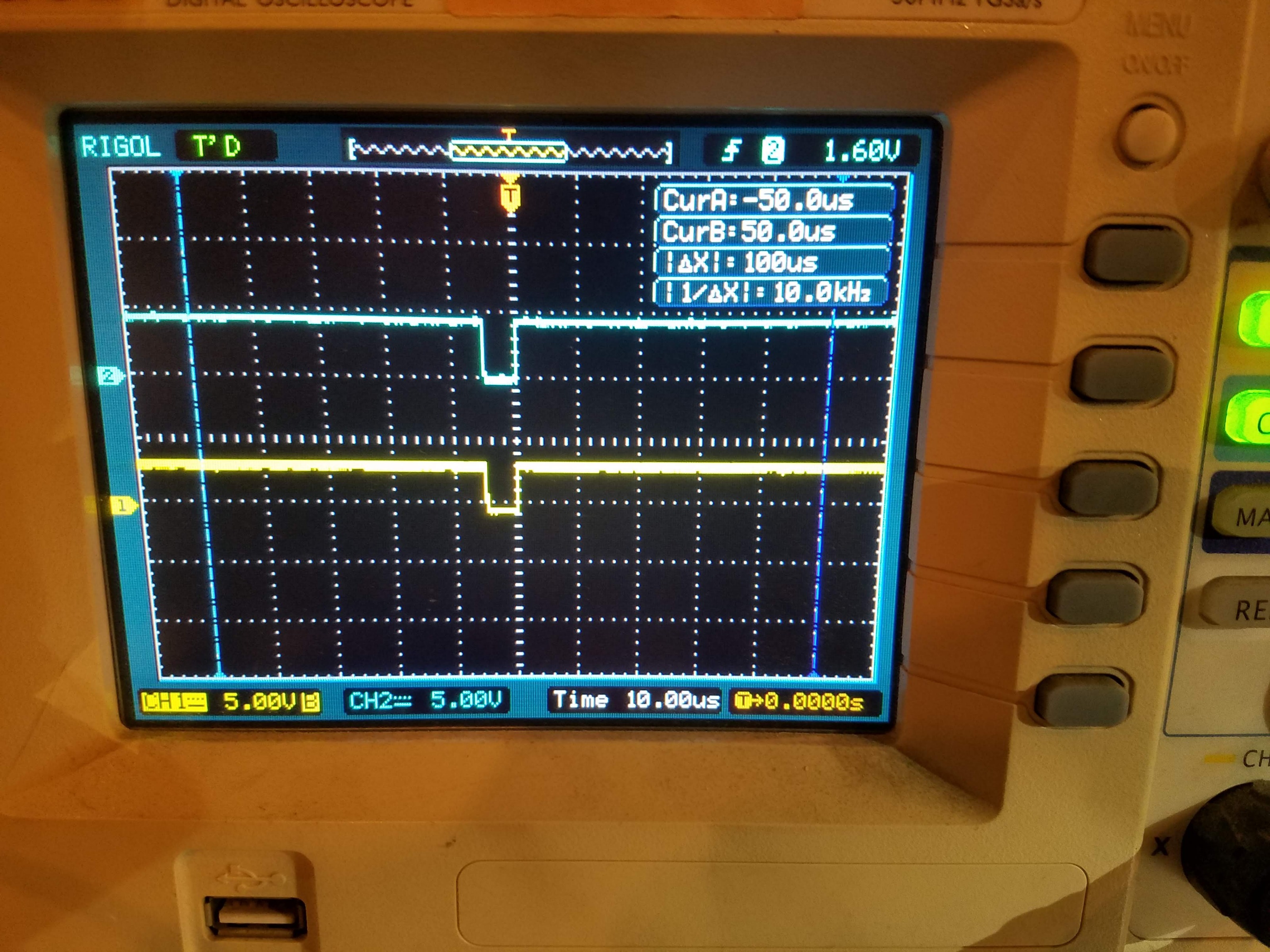
The pulses are lined up with each other on most of the axes, but in the same direction so they look like they'd cancel each other out. Some of the axes don't seem to be sending pulses at all, though, so we're really confused. Any clues as to what has gone wrong between 2 days ago and today? Any help is appreciated.
Today we started the swap over to the new system again. And it was immensely painful. At first only 2 of the 8 axes worked. Very perplexing. We noticed that the case was at +24V so we chased down a loose wire from the swap. However, now none of the axes are functioning. We decided to pull out the o-scope and look at the pulses...
The pulses are lined up with each other on most of the axes, but in the same direction so they look like they'd cancel each other out. Some of the axes don't seem to be sending pulses at all, though, so we're really confused. Any clues as to what has gone wrong between 2 days ago and today? Any help is appreciated.
Please Log in or Create an account to join the conversation.
- PCW
-

- Offline
- Moderator
-

Less
More
- Posts: 17977
- Thank you received: 5275
28 Nov 2018 23:44 #121563
by PCW
Replied by PCW on topic 7i76e with 7i85S to control 9 steppers
what are the signals you are displaying?
Please Log in or Create an account to join the conversation.
- cogzoid
-
Topic Author
- Visitor
-
29 Nov 2018 00:11 #121566
by cogzoid
Replied by cogzoid on topic 7i76e with 7i85S to control 9 steppers
Sorry for not being clear. Those are the Step+ and Step- signals while we're driving the X axis.
Are those the pulses that we should be expecting?
-D
Are those the pulses that we should be expecting?
-D
Please Log in or Create an account to join the conversation.
- PCW
-
- Offline
- Moderator
-
Less
More
- Posts: 17977
- Thank you received: 5275
29 Nov 2018 00:28 - 29 Nov 2018 00:30 #121568
by PCW
Replied by PCW on topic 7i76e with 7i85S to control 9 steppers
No, the step+ and step- pins should be inversions of each other
If they are not (with no load to exclude wiring issues) then the driver chips may have gotten damaged somehow
Any external power source > than about 12V inadvertently shorted to the step/dir outputs
will damage the output driver chips or the 27 Ohm output series resistor networks
If they are not (with no load to exclude wiring issues) then the driver chips may have gotten damaged somehow
Any external power source > than about 12V inadvertently shorted to the step/dir outputs
will damage the output driver chips or the 27 Ohm output series resistor networks
Last edit: 29 Nov 2018 00:30 by PCW.
Please Log in or Create an account to join the conversation.
- cogzoid
-
Topic Author
- Visitor
-
29 Nov 2018 00:44 - 29 Nov 2018 00:44 #121569
by cogzoid
Replied by cogzoid on topic 7i76e with 7i85S to control 9 steppers
We have a second 7i76e board that we bought for a second project. We flashed it, swapped it into place, and it works just fine. So we must've accidentally fried this board while we were swapping out wires and checking things... Ugh. The problem is that we don't have a second 7i85s on hand, and that one isn't putting out signals.
Is there some check that we can do on these boards to confirm that they're broken?
Is there some check that we can do on these boards to confirm that they're broken?
Last edit: 29 Nov 2018 00:44 by cogzoid.
Please Log in or Create an account to join the conversation.
- andypugh
-

- Offline
- Moderator
-
Less
More
- Posts: 19875
- Thank you received: 4642
30 Nov 2018 15:49 #121638
by andypugh
You can disable all stepgens so that the outputs become GPIO and then see if it is possible to change the value from the command line.
You can now set the value of IO pins one by one:
The "show pin" command will give a pin listing.
More info here:
linuxcnc.org/docs/2.7/html/man/man9/host...eral%20Purpose%20I/O
Replied by andypugh on topic 7i76e with 7i85S to control 9 steppers
Is there some check that we can do on these boards to confirm that they're broken?
You can disable all stepgens so that the outputs become GPIO and then see if it is possible to change the value from the command line.
halrun
loadrt hostmot2
loadrt hm2_pci config="num_encoders=0"
loadrt threads
addf hm2_5i25.0.read thread1
addf hm2_5i25.0.write thread1
start
You can now set the value of IO pins one by one:
show pin
setp hm2_5i25.0.gpio.025.is_output 1
setp hm2_5i25.0.gpio.025 1
setp hm2_5i25.0.gpio.025 0
The "show pin" command will give a pin listing.
More info here:
linuxcnc.org/docs/2.7/html/man/man9/host...eral%20Purpose%20I/O
Please Log in or Create an account to join the conversation.
Moderators: cmorley
Time to create page: 0.183 seconds