Probe Calibration Renishaw MP12
- perra_e
- Offline
- Senior Member
-

Less
More
- Posts: 73
- Thank you received: 1
26 Aug 2020 13:47 #179542
by perra_e
Replied by perra_e on topic Probe Calibration Renishaw MP12
Hi Sviper,
It would help very much!
I have started to try to create a replica of the macros, but it's a heck of a job!
It would help very much!
I have started to try to create a replica of the macros, but it's a heck of a job!
Please Log in or Create an account to join the conversation.
- tecno
-

- Offline
- Platinum Member
-

Less
More
- Posts: 1850
- Thank you received: 127
26 Aug 2020 14:15 - 26 Aug 2020 14:15 #179544
by tecno
Replied by tecno on topic Probe Calibration Renishaw MP12
Hello Sviper,
Yes it would very helpful to be able to run these in LCNC.
Yes it would very helpful to be able to run these in LCNC.
Last edit: 26 Aug 2020 14:15 by tecno.
Please Log in or Create an account to join the conversation.
- Sviper
- Offline
- Senior Member
-
Less
More
- Posts: 77
- Thank you received: 9
27 Aug 2020 04:10 #179645
by Sviper
Replied by Sviper on topic Probe Calibration Renishaw MP12
Hello
I would make them available to you, but I would not like to post them here in the forum.
I don't know what kind of license rights are on it.
Is there a possibility to send a PN here in the forum? I can't find this function.
Greetings
I would make them available to you, but I would not like to post them here in the forum.
I don't know what kind of license rights are on it.
Is there a possibility to send a PN here in the forum? I can't find this function.
Greetings
Please Log in or Create an account to join the conversation.
- tecno
-
- Offline
- Platinum Member
-
Less
More
- Posts: 1850
- Thank you received: 127
27 Aug 2020 08:20 - 27 Aug 2020 11:09 #179669
by tecno
Replied by tecno on topic Probe Calibration Renishaw MP12
There is no PM function here on the forum.
you can send email to me
you can send email to me
Last edit: 27 Aug 2020 11:09 by tecno.
Please Log in or Create an account to join the conversation.
- Sviper
- Offline
- Senior Member
-
Less
More
- Posts: 77
- Thank you received: 9
14 Nov 2020 08:30 #189304
by Sviper
Replied by Sviper on topic Probe Calibration Renishaw MP12
Hello Plopes9000
can you send us the xminus, xplus, yminus, yplus files with the integration.
I'm not sure how i have to edit the files.
sorry i'm a beginner.
Thanks
Thank
can you send us the xminus, xplus, yminus, yplus files with the integration.
I'm not sure how i have to edit the files.
sorry i'm a beginner.
Thanks
Thank
Please Log in or Create an account to join the conversation.
- Sviper
- Offline
- Senior Member
-
Less
More
- Posts: 77
- Thank you received: 9
23 Nov 2020 13:34 #190112
by Sviper
Replied by Sviper on topic Probe Calibration Renishaw MP12
hello
can anyone provide the files? xminus, xplus, yminus, yplus e
can anyone provide the files? xminus, xplus, yminus, yplus e
Please Log in or Create an account to join the conversation.
- plopes9000
-
 Topic Author
- Offline
- Premium Member
-

Less
More
- Posts: 87
- Thank you received: 18
19 Feb 2021 20:25 #199472
by plopes9000
Replied by plopes9000 on topic Probe Calibration Renishaw MP12
checkout the original post, I've just updated it.
Please Log in or Create an account to join the conversation.
- plopes9000
-
Topic Author
- Offline
- Premium Member
-
Less
More
- Posts: 87
- Thank you received: 18
19 Feb 2021 20:27 - 19 Feb 2021 20:28 #199473
by plopes9000
Checkout the original post, I've just updated it - I believe the integration with probe screen is now taking into account the calibration values.
Replied by plopes9000 on topic Probe Calibration Renishaw MP12
I'm not having success integrating this code with probe screen as suggested.
I believe the probe screen python code is using linuxcnc call stat.probe_position() to identify where the probe was triggered after each move.
Since the code supplied pulls variables #621-#628 (offsets) through a Gcode subroutine and adjusts the measured probe value within the subroutine into variable 5001 and 5002 probe screen is missing the offset.
Anyone else have this issue? Are variables 5001 and 5002 special? Maybe i'm missing something.
**EDIT - I think i understand . This code is attempting to change the absolute position on the mill before probe screen has a chance to read it. Isn't that dangerous? Would it not throw off the homed location? Probe screen still would never get the result because it is determining the probe trip point from the previous G38.2 calls which do not include the offset table variables.
The probing calibration routine worked great. I agree with what was calculated. Thank you plopes9000 for your efforts!
Checkout the original post, I've just updated it - I believe the integration with probe screen is now taking into account the calibration values.
Last edit: 19 Feb 2021 20:28 by plopes9000.
Please Log in or Create an account to join the conversation.
- ZincBoy
- Offline
- Junior Member
-

Less
More
- Posts: 34
- Thank you received: 15
20 Feb 2021 05:02 #199496
by ZincBoy
Replied by ZincBoy on topic Probe Calibration Renishaw MP12
I have been working on adding some probe calibration buttons to probe screen (and other improvements) as well as some probe characterization functions. plopes9000's post was an inspiration to work on this. The main reason for me to work on this was because I wanted to add support for automatic xy error removal when spindle orientation is present. So far I have both sphere and ring gauge calibration standards working with an arbitrary number of calibration points.
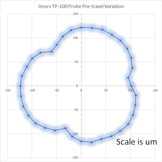
Data was gathered with 10 touches each at 10 degree increments. The 10 touches were averaged to remove contact variation and also used to determine the variation. The pre-travel plot is the probe error when using the physical probe ball diameter and not the corrected diameter. The residual error is after the probe pre-travel has been removed by using the electrical probe ball diameter instead. The shading in the plots indicates the 95% confidence interval. All plots have probe center alignment calibration applied.
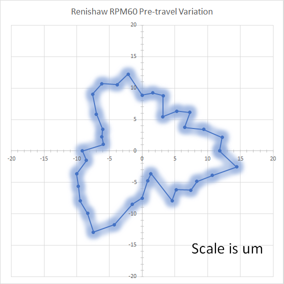
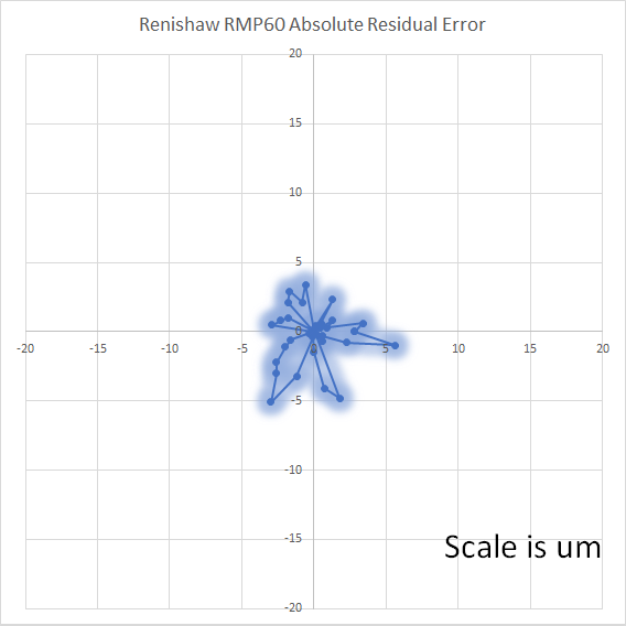
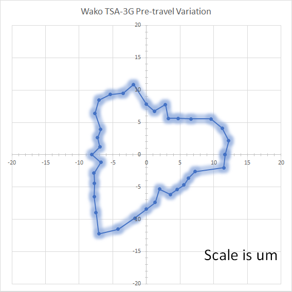
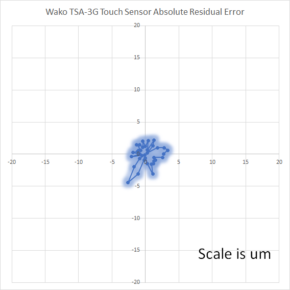

As my machine has 1um resolution on the encoders I consider anything around 5um to be good enough. Both the renishaw and wako probes were able to be calibrated to around 5um with a x-y offset and probe ball diameter correction as seen in the residual plots. The 95% confidence variation on both probes was about 1.2um so they are likely repeating better than I can measure on my machine. Both probes are good to 15um with only x-y calibration.
For the Imsrv TP-100 the story is a bit different. This probe is a low cost unit priced at about $250 that I picked up many years ago when I started out with a Taig CNC. I think it would be fairly representative of hobbyist level probes. It is a simple switch with no resistive sensing as is used in the renishaw to improve sensitivity. This is apparent in the pre-travel plot where the travel to trip is around 120um. The variation is also much higher with a average 95% confidence variation of 4um and a maximum of 10um. Probe diameter calibration is required for this probe to be accurate on just about any machine. After probe diameter calibration there is still about 20um of error. It would be possible to compensate this using either a curve fitting or multi point approach. I was thinking of implementing a multi point calibration but I am not sure how many would benefit from it. It would only apply when using a low cost probe on an high resolution machine.
PS Yes I know they should be polar plots but I haven't figured out plotting in python yet and excel doesn't have polar plots")
Data was gathered with 10 touches each at 10 degree increments. The 10 touches were averaged to remove contact variation and also used to determine the variation. The pre-travel plot is the probe error when using the physical probe ball diameter and not the corrected diameter. The residual error is after the probe pre-travel has been removed by using the electrical probe ball diameter instead. The shading in the plots indicates the 95% confidence interval. All plots have probe center alignment calibration applied.
As my machine has 1um resolution on the encoders I consider anything around 5um to be good enough. Both the renishaw and wako probes were able to be calibrated to around 5um with a x-y offset and probe ball diameter correction as seen in the residual plots. The 95% confidence variation on both probes was about 1.2um so they are likely repeating better than I can measure on my machine. Both probes are good to 15um with only x-y calibration.
For the Imsrv TP-100 the story is a bit different. This probe is a low cost unit priced at about $250 that I picked up many years ago when I started out with a Taig CNC. I think it would be fairly representative of hobbyist level probes. It is a simple switch with no resistive sensing as is used in the renishaw to improve sensitivity. This is apparent in the pre-travel plot where the travel to trip is around 120um. The variation is also much higher with a average 95% confidence variation of 4um and a maximum of 10um. Probe diameter calibration is required for this probe to be accurate on just about any machine. After probe diameter calibration there is still about 20um of error. It would be possible to compensate this using either a curve fitting or multi point approach. I was thinking of implementing a multi point calibration but I am not sure how many would benefit from it. It would only apply when using a low cost probe on an high resolution machine.
PS Yes I know they should be polar plots but I haven't figured out plotting in python yet and excel doesn't have polar plots
Attachments:
The following user(s) said Thank You: plopes9000
Please Log in or Create an account to join the conversation.
- plopes9000
-
Topic Author
- Offline
- Premium Member
-
Less
More
- Posts: 87
- Thank you received: 18
20 Feb 2021 05:44 #199497
by plopes9000
Replied by plopes9000 on topic Probe Calibration Renishaw MP12
Nice plots, as the saying goes, a picture is worth a thousand words, this is certainly the case here. The plots tell the whole story.
Please Log in or Create an account to join the conversation.
Time to create page: 0.278 seconds