Setting up USB -> Modbus (CH340) for VFD control
- Victor
-
 Topic Author
- Offline
- Senior Member
-

- Posts: 51
- Thank you received: 1
Ok, i got awesome help in my previous thread on how i would tackle my journey into LinuxCNC, so off i went and got a ASRock card with db25 connector, a BOB etc.
And i was expecting a rough entry but, i got the Live CD, followed the installation guide, got it working, did the StepConf Wizard, plugged in the BOB and amazingly it worked, i can detect Estop, limit switches etc. so i'm impressed!
However my next task on my to-do list got me pulling my hair a little bit so i would need some guidance

i was recommended to go for a USB -> Modbus dongle for VFD control and i thought it sounded great, so i got a CH340 dongle, and i thought i would need to tick a box in the configuration "Use Modbus" but to my great surprise it is much more complicated and out of my existing knowledge zone.
I have searched the forum, wiki, docs, google but it is still not clear for me. should i use HAL? or Classic Ladder?
i have read wiki.linuxcnc.org/cgi-bin/wiki.pl?VFD_Modbus and wiki.linuxcnc.org/cgi-bin/wiki.pl?ModbusToHal
this chapter got me stucked:
Create a directory under "/home/my_home/emc2" such as "/home/my_home/emc2/my_vfd" (this line i understnad
 )
)Copy into "my_vfd" a sample vfd.c, modbus.c, modbus.h, and Makefile
Edit my_vfd-x.c and Makefile
Run "cp my_vfd-x my_vfd.c", "make", "sudo make install"
Copy sample linuxcnc config files in "/home/my_home/emc2/configs/myCNC/"
Edit the .hal file in "...myCNC/myCNC.hal" to "loadusr my_vfd ..." and connect HAL pins
Invoke emc2 and enjoy
sample vfd.c, modbus.c modbus.h are these empty documents i create? what is Makerfile?
So if somebody could help me get thru this it would be very appreciated!
The below link is a couple pages on the modbus section from my ENC EN600 VFD.
VFD Modbus manual
Thanks!
// Victor
Please Log in or Create an account to join the conversation.
- Todd Zuercher
-

- Away
- Platinum Member
-

- Posts: 4761
- Thank you received: 1463
linuxcnc.org/docs/html/drivers/mb2hal.html
I'm sure there are some sample MB2HAL configs floating around in the forum that you could look up. (I know I've posted a couple of them). If you can't find anything let me know and I'll see if I can dig up a simple example. (What I have running on the machine would not be considered a simple example as it is controlling 8 VFDs.)
If you still have questions please ask.
Please Log in or Create an account to join the conversation.
- Victor
-
Topic Author
- Offline
- Senior Member
-
- Posts: 51
- Thank you received: 1
i will check some examples out and see if i can make any sense from it ;D
Thanks!
Victor
Please Log in or Create an account to join the conversation.
- Victor
-
Topic Author
- Offline
- Senior Member
-
- Posts: 51
- Thank you received: 1
a .ini file for the MB2hal component?
i have named my .ini file to "mb2hal.ini" and posted the below code frome the linuxcnc.org/docs/html/drivers/mb2hal.html page
#This .INI file is also the HELP, MANUAL and HOW-TO file for mb2hal.

#Load the modbus HAL userspace module as the examples below,
#change to match your own HAL_MODULE_NAME and .ini file name
#Using HAL_MODULE_NAME=mb2hal or nothing (default): loadusr -W mb2hal config=config_file.ini
#Using HAL_MODULE_NAME=mymodule: loadusr -Wn mymodule mb2hal config=config_file.ini

#Common section

[MB2HAL_INIT]

#OPTIONAL: Debug level of init and INI file parsing.
# 0 = silent.
# 1 = error messages (default).
# 2 = OK confirmation messages.
# 3 = debugging messages.

INIT_DEBUG=3

#OPTIONAL: HAL module (component) name. Defaults to "mb2hal".

HAL_MODULE_NAME=mb2hal

#OPTIONAL: Insert a delay of "FLOAT seconds" between transactions in order
#to not to have a lot of logging and facilitate the debugging.
#Usefull when using DEBUG=3 (NOT INIT_DEBUG=3)
#It affects ALL transactions.
#Use "0.0" for normal activity.

SLOWDOWN=0.0

#REQUIRED: The number of total Modbus transactions. There is no maximum.

TOTAL_TRANSACTIONS=9

#One transaction section is required per transaction, starting at 00 and counting up sequentially.
#If there is a new link (not transaction), you must provide the REQUIRED parameters 1st time.
#Warning: Any OPTIONAL parameter not specified are copied from the previous transaction.

[TRANSACTION_00]

#REQUIRED: You must specify either a "serial" or "tcp" link for the first transaction.
#Later transaction will use the previous transaction link if not specified.

LINK_TYPE=tcp

#if LINK_TYPE=tcp then REQUIRED (only 1st time): The Modbus slave device ip address.
#if LINK_TYPE=serial then IGNORED

TCP_IP=192.168.2.10

#if LINK_TYPE=tcp then OPTIONAL.
#if LINK_TYPE=serial then IGNORED
#The Modbus slave device tcp port. Defaults to 502.

TCP_PORT=502

#if LINK_TYPE=serial then REQUIRED (only 1st time).
#if LINK_TYPE=tcp then IGNORED
#The serial port.

SERIAL_PORT=/dev/ttyS0

#if LINK_TYPE=serial then REQUIRED (only 1st time).
#if LINK_TYPE=tcp then IGNORED
#The baud rate.

SERIAL_BAUD=115200

#if LINK_TYPE=serial then REQUIRED (only 1st time).
#if LINK_TYPE=tcp then IGNORED
#Data bits. One of 5,6,7,8.

SERIAL_BITS=8

#if LINK_TYPE=serial then REQUIRED (only 1st time).
#if LINK_TYPE=tcp then IGNORED
#Data parity. One of: even, odd, none.

SERIAL_PARITY=none

#if LINK_TYPE=serial then REQUIRED (only 1st time).
#if LINK_TYPE=tcp then IGNORED
#Stop bits. One of 1, 2.

SERIAL_STOP=2

#if LINK_TYPE=serial then OPTIONAL:
#if LINK_TYPE=tcp then IGNORED
#Serial port delay between for this transaction only.
#In ms. Defaults to 0.

SERIAL_DELAY_MS=10

#REQUIRED (only 1st time).
#Modbus slave number.

MB_SLAVE_ID=1

#REQUIRED: The first element address.

FIRST_ELEMENT=0

#REQUIRED: The number of elements.

NELEMENTS=16

#REQUIRED: Modbus transaction function code (see www.modbus.org specifications).
#    fnct_02_read_discrete_inputs     (02 = 0x02)
#    fnct_03_read_holding_registers   (03 = 0x03)
#    fnct_04_read_input_registers     (04 = 0x04)
#    fnct_15_write_multiple_coils     (15 = 0x0F)
#    fnct_16_write_multiple_registers (16 = 0x10)

#fnct_02_read_discrete_inputs: creates boolean output HAL pins.
#fnct_03_read_holding_registers: creates a floating point output HAL pins.
#                           also creates a u32 output HAL pins.
#fnct_04_read_input_registers: creates a floating point output HAL pins.
#                         also creates a u32 output HAL pins.
#fnct_15_write_multiple_coils: creates boolean input HAL pins.
#fnct_16_write_multiple_registers: creates a floating point input HAL pins.

#The pins are named based on component name, transaction number and order number.
#Example: mb2hal.00.01 (transaction=00, second register=01 (00 is the first one))

MB_TX_CODE=fnct_03_read_holding_registers

#OPTIONAL: Response timeout for this transaction. In INTEGER ms. Defaults to 500 ms.
#This is how much to wait for 1st byte before raise an error.

MB_RESPONSE_TIMEOUT_MS=500

#OPTIONAL: Byte timeout for this transaction. In INTEGER ms. Defaults to 500 ms.
#This is how much to wait from byte to byte before raise an error.

MB_BYTE_TIMEOUT_MS=500

#OPTIONAL: Instead of giving the transaction number, use a name.
#Example: mb2hal.00.01 could become mb2hal.plcin.01
#The name must not exceed 32 characters.
#NOTE: when using names be careful that you dont end up with two transactions
#usign the same name.

HAL_TX_NAME=remoteIOcfg

#OPTIONAL: Maximum update rate in HZ. Defaults to 0.0 (0.0 = as soon as available = infinit).
#NOTE: This is a maximum rate and the actual rate may be lower.
#If you want to calculate it in ms use (1000 / required_ms).
#Example: 100 ms = MAX_UPDATE_RATE=10.0, because 1000.0 ms / 100.0 ms = 10.0 Hz

MAX_UPDATE_RATE=0.0

#OPTIONAL: Debug level for this transaction only.
#See INIT_DEBUG parameter above.

DEBUG=1

#While DEBUGGING transactions note the returned "ret[]" value correspond to:
#/* Modbus protocol exceptions */
#ILLEGAL_FUNCTION        -0x01 the FUNCTION code received in the query is not allowed or invalid.
#ILLEGAL_DATA_ADDRESS    -0x02 the DATA ADDRESS received in the query is not an allowable address for the slave or is invalid.
#ILLEGAL_DATA_VALUE      -0x03 a VALUE contained in the data query field is not an allowable value or is invalid.
#SLAVE_DEVICE_FAILURE    -0x04 SLAVE (or MASTER) device unrecoverable FAILUER while attemping to perform the requested action.
#SERVER_FAILURE          -0x04 (see above).
#ACKNOWLEDGE             -0x05 This response is returned to PREVENT A TIMEOUT in the master.
#                              A long duration of time is required to process the request in the slave.
#SLAVE_DEVICE_BUSY       -0x06 The slave (or server) is BUSY. Retrasmit the request later.
#SERVER_BUSY             -0x06 (see above).
#NEGATIVE_ACKNOWLEDGE    -0x07 Unsuccessful programming request using function code 13 or 14.
#MEMORY_PARITY_ERROR     -0x08 SLAVE parity error in MEMORY.
#GATEWAY_PROBLEM_PATH    -0x0A (-10) Gateway path(s) not available.
#GATEWAY_PROBLEM_TARGET  -0x0B (-11) The target device failed to repond (generated by master, not slave).
#/* Program or connection */
#COMM_TIME_OUT           -0x0C (-12)
#PORT_SOCKET_FAILURE     -0x0D (-13)
#SELECT_FAILURE          -0x0E (-14)
#TOO_MANY_DATAS          -0x0F (-15)
#INVALID_CRC             -0x10 (-16)
#INVALID_EXCEPTION_CODE  -0x11 (-17)

[TRANSACTION_01]
MB_TX_CODE=fnct_02_read_discrete_inputs
FIRST_ELEMENT=1024
NELEMENTS=24
HAL_TX_NAME=remoteIOin
MAX_UPDATE_RATE=0.0
DEBUG=1

[TRANSACTION_02]
MB_TX_CODE=fnct_15_write_multiple_coils
FIRST_ELEMENT=1280
NELEMENTS=8
HAL_TX_NAME=remoteIOout
MAX_UPDATE_RATE=0.0

[TRANSACTION_03]
LINK_TYPE=serial
SERIAL_PORT=/dev/ttyS0
SERIAL_BAUD=115200
SERIAL_BITS=8
SERIAL_PARITY=none
SERIAL_STOP=2
SERIAL_DELAY_MS=50
MB_SLAVE_ID=1
MB_TX_CODE=fnct_03_read_holding_registers
FIRST_ELEMENT=1
NELEMENTS=2
HAL_TX_NAME=XDrive01
MAX_UPDATE_RATE=0.0
DEBUG=1

[TRANSACTION_04]
MB_TX_CODE=fnct_03_read_holding_registers
FIRST_ELEMENT=4
NELEMENTS=3
HAL_TX_NAME=XDrive02
MAX_UPDATE_RATE=0.0
DEBUG=1

[TRANSACTION_05]
MB_TX_CODE=fnct_03_read_holding_registers
FIRST_ELEMENT=9
NELEMENTS=1
HAL_TX_NAME=XDrive03
MAX_UPDATE_RATE=0.0

[TRANSACTION_06]
MB_TX_CODE=fnct_03_read_holding_registers
FIRST_ELEMENT=1024
NELEMENTS=1
HAL_TX_NAME=XDrive04
MAX_UPDATE_RATE=0.0

[TRANSACTION_07]
MB_TX_CODE=fnct_03_read_holding_registers
FIRST_ELEMENT=1030
NELEMENTS=2
HAL_TX_NAME=XDrive05
MAX_UPDATE_RATE=0.0

[TRANSACTION_08]
MB_TX_CODE=fnct_03_read_holding_registers
FIRST_ELEMENT=1033
NELEMENTS=1
HAL_TX_NAME=XDrive06
MAX_UPDATE_RATE=0.0
and then i need to put the following lines in my custom.hal file:
loadusr -W mb2hal config=mb2hal.ini
loadusr -Wn mymodule mb2hal config=config_file.ini <- i guess i should make a .ini file for my vfd like "enc_vfd.ini" ?
so the second line should perhaps be: loadusr -Wn enc_vfd mb2hal config=enc_vfd.ini ?
and in this "enc_vfd.ini" file i need to put the modbus translation code?
i looked for some examples and i found one on a X200 Hitachi inverter,
some of it makes sense to me but i'm uncertain what i need to change for my application?
below is the X200 .ini file
[MB2HAL_INIT]
INIT_DEBUG=0
.
HAL_MODULE_NAME=x200-vfd
SLOWDOWN=0.0
TOTAL_TRANSACTIONS=10

# Set Run Status
[TRANSACTION_00]
LINK_TYPE=serial
SERIAL_PORT=/dev/ttyS0
SERIAL_BAUD=9600
SERIAL_BITS=8
SERIAL_PARITY=none
SERIAL_STOP=1
SERIAL_DELAY_MS=3
MB_SLAVE_ID=1

FIRST_ELEMENT=0
NELEMENTS=1
MB_TX_CODE=fnct_15_write_multiple_coils
HAL_TX_NAME=run
MAX_UPDATE_RATE=0.0
DEBUG=3

# Set Direction
[TRANSACTION_01]
MB_TX_CODE=fnct_15_write_multiple_coils
FIRST_ELEMENT=1
NELEMENTS=1
HAL_TX_NAME=direction
MAX_UPDATE_RATE=0.0
DEBUG=3

# Set Frequency
[TRANSACTION_02]
MB_TX_CODE=fnct_16_write_multiple_registers
FIRST_ELEMENT=0
NELEMENTS=1
HAL_TX_NAME=set-frequency
MAX_UPDATE_RATE=0.0
DEBUG=3

# Spindle Running?
[TRANSACTION_03]
MB_TX_CODE=fnct_15_write_multiple_coils
FIRST_ELEMENT=13
NELEMENTS=1
HAL_TX_NAME=is-running
MAX_UPDATE_RATE=0.0
DEBUG=3

# Running Clockwise?
[TRANSACTION_04]
MB_TX_CODE=fnct_15_write_multiple_coils
FIRST_ELEMENT=14
NELEMENTS=1
HAL_TX_NAME=is-reverse
MAX_UPDATE_RATE=0.0
DEBUG=3

# Is at Speed?
[TRANSACTION_05]
MB_TX_CODE=fnct_15_write_multiple_coils
FIRST_ELEMENT=24
NELEMENTS=1
HAL_TX_NAME=is-at-speed
MAX_UPDATE_RATE=0.0
DEBUG=3

# Is Alarm?
[TRANSACTION_06]
MB_TX_CODE=fnct_15_write_multiple_coils
FIRST_ELEMENT=19
NELEMENTS=1
HAL_TX_NAME=is-alarm
MAX_UPDATE_RATE=0.0
DEBUG=3

# Is Ready?
[TRANSACTION_07]
MB_TX_CODE=fnct_15_write_multiple_coils
FIRST_ELEMENT=16
NELEMENTS=1
HAL_TX_NAME=is-ready
MAX_UPDATE_RATE=0.0
DEBUG=3

# Is External Trip active?
[TRANSACTION_08]
MB_TX_CODE=fnct_15_write_multiple_coils
FIRST_ELEMENT=5
NELEMENTS=1
HAL_TX_NAME=is-tripped
MAX_UPDATE_RATE=0.0
DEBUG=3

# Reset VFD
[TRANSACTION_09]
MB_TX_CODE=fnct_15_write_multiple_coils
FIRST_ELEMENT=6
NELEMENTS=1
HAL_TX_NAME=reset
MAX_UPDATE_RATE=0.0
DEBUG=3

 #REQUIRED: Modbus transaction function code (see www.modbus.org specifications).
 #    fnct_02_read_discrete_inputs     (02 = 0x02)
 #    fnct_03_read_holding_registers   (03 = 0x03)
 #    fnct_04_read_input_registers     (04 = 0x04)
 #    fnct_15_write_multiple_coils     (15 = 0x0F)
 #    fnct_16_write_multiple_registers (16 = 0x10)
 #fnct_02_read_discrete_inputs: creates boolean output HAL pins.
 #fnct_03_read_holding_registers: creates a floating point output HAL pins.
 #                           also creates a u32 output HAL pins.
 #fnct_04_read_input_registers: creates a floating point output HAL pins.
 #                         also creates a u32 output HAL pins.
 #fnct_15_write_multiple_coils: creates boolean input HAL pins.
 #fnct_16_write_multiple_registers: creates a floating point input HAL pins.
 #The pins are named based on component name, transaction number and order number.
 #Example: mb2hal.00.01 (transaction=00, second register=01 (00 is the first one))
Thanks!
Victor
Please Log in or Create an account to join the conversation.
- Todd Zuercher
-
- Away
- Platinum Member
-
- Posts: 4761
- Thank you received: 1463
and then i need to put the following lines in my custom.hal file:
loadusr -W mb2hal config=mb2hal.ini
loadusr -Wn mymodule mb2hal config=config_file.ini <- i guess i should make a .ini file for my vfd like "enc_vfd.ini" ?
No, those are 2 possible options for the line of code you need in your hal file.
Keep it simple and only use the top line.
You only need one modbus ini file, so you only need to keep your mb2hal.ini or your enc_vfd.ini (not both).
If you use enc_vfd.ini for the config file name you will need to change the line in your hal file to" loadusr -W mb2hal config=enc_vfd.ini"
Just remember the mb2hal.ini file has a lot of unnecessary info, lots of comments, optional settings, and commented out examples included. It can be difficult to sort through it all to see just what you need and don't need. That is where other examples like the X200 one you posted come in handy. You are going to have to carefully read through the manuals for your drive to determine what all the settings are going to be both in mb2hal and in the drive its self. Every drive manufacturer uses different protocols so you can't just copy what works for a different drive.
It took me a couple of weeks to sort it all out for the drives I was using, even with decent manuals. If you can't get the modbus manuals for your drives you might be out of luck.
Please Log in or Create an account to join the conversation.
- Victor
-
Topic Author
- Offline
- Senior Member
-
- Posts: 51
- Thank you received: 1
So i should go
loadusr -W mb2hal config=enc_vfd.ini
do i need antything else in the .hal file?
this was a chapter in the X200 thread (code from the .hal file) that catched my eye:
net x200-run x200.run.00 <= motion.spindle-on
net x200-dir x200.direction.00 <= motion.spindle-forward
net x200-RPM x200.frequency.00 <= motion.spindle-speed-out
net x200-at-speed x200.at-speed.00 <= motion.spindle-at-speed
setp x200.direction.00 0
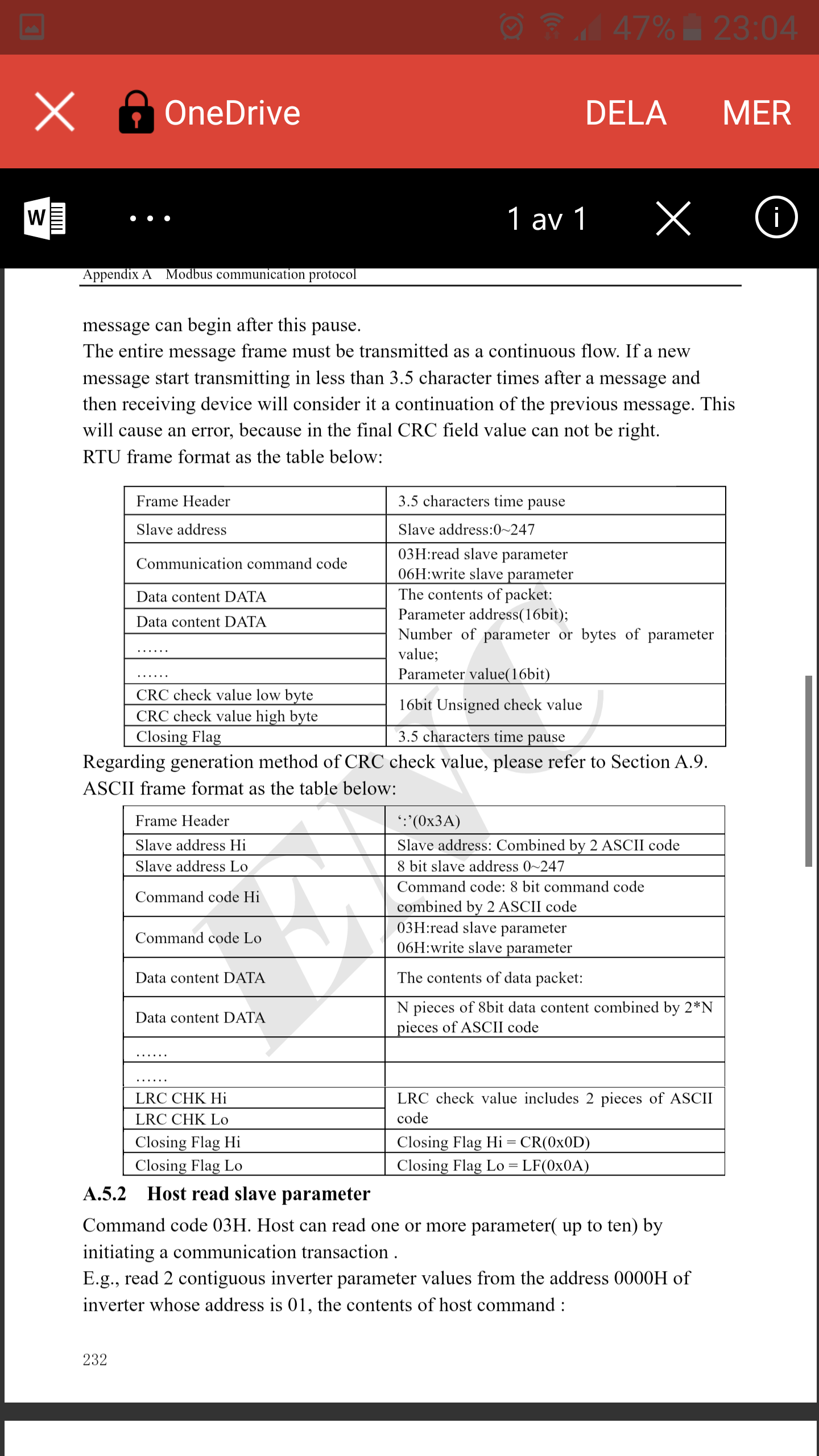
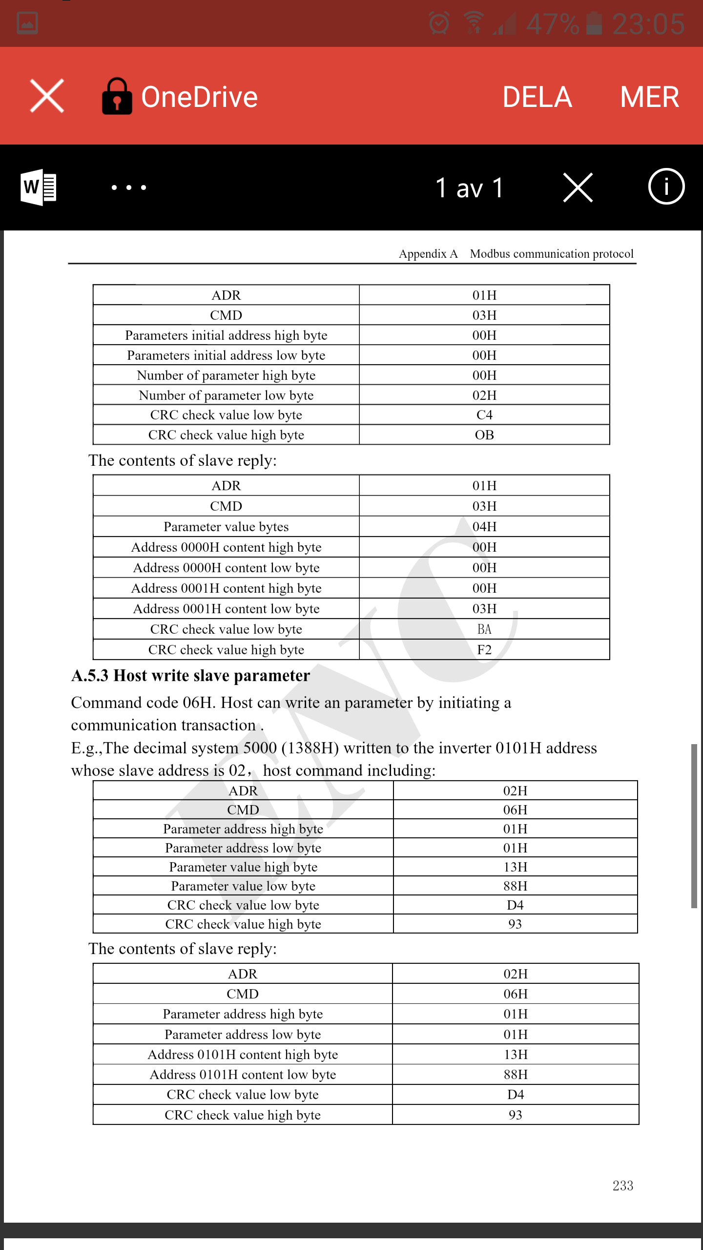
Well the manual is really good for my vfd, i separated the modbus part that can be located here: 1drv.ms/b/s!AnY9CcWCLBtalGev69rQ1UOUzZXn
i just don't understand how i should apply the information from the manual, if we look at this chapter from the X200 code for example:
# Running Clockwise?
[TRANSACTION_04]
MB_TX_CODE=fnct_15_write_multiple_coils
FIRST_ELEMENT=14
NELEMENTS=1
HAL_TX_NAME=is-reverse
MAX_UPDATE_RATE=0.0
DEBUG=3
i have this table in the manual:

Victor
Please Log in or Create an account to join the conversation.
- Todd Zuercher
-
- Away
- Platinum Member
-
- Posts: 4761
- Thank you received: 1463
Such as my drives need to have a certain register written to to unlock the drive. Then another had to be read periodically to prevent a communications shut down... I'm a little jealous if you only need to write to one register and read 2 contiguous ones. (Did i mention the drives I had to work with were a complicated mess.)
Please Log in or Create an account to join the conversation.
- Victor
-
Topic Author
- Offline
- Senior Member
-
- Posts: 51
- Thank you received: 1
Would be super if you could explain how i would need to code for one function like running clockwise
Victor
Please Log in or Create an account to join the conversation.
- Todd Zuercher
-
- Away
- Platinum Member
-
- Posts: 4761
- Thank you received: 1463
The first thing you need to do is figure out what the drives current modbus parameter settings are, and what you need to set them to.
You need to figure out what the address of your little USB dongle is. (It should be something like SERIAL_PORT=/dev/ttyUSB0 (or 1,2 3...) Mine was 0 as it it the only USB device on that computer.
Please Log in or Create an account to join the conversation.
- Victor
-
Topic Author
- Offline
- Senior Member
-
- Posts: 51
- Thank you received: 1
I have the following pages with diffrent protocols if that is what you mean?

Please Log in or Create an account to join the conversation.