DM542A / DB25-1205 Probable wiring issue
- vfontaine
- Offline
- New Member
-

Less
More
- Posts: 3
- Thank you received: 0
18 Mar 2018 03:00 - 18 Mar 2018 03:02 #107483
by vfontaine
DM542A / DB25-1205 Probable wiring issue was created by vfontaine
Hello everybody.
I purchased a set of 4 DM542A drives and a break out board DB25-1205 but I still cannot have a motor running.
A. materiel
I will break down every informations I have hoping someone will dig out the problem.
Here is the videos I followed to do the wiring and configurations :
A.1.The computer I use is a Dell optiplex 745
the jitter I found on the internet is the first value and the one given by LinuxCNC is the second
Max interval (1,0 ms thread) 1064158 / 1039109
Max jitter (1,0 ms thread) 64918 / 42229
Max interval (25 micro second) 49610 / 45275
Max interval (25 micro second) 24629 / 20353
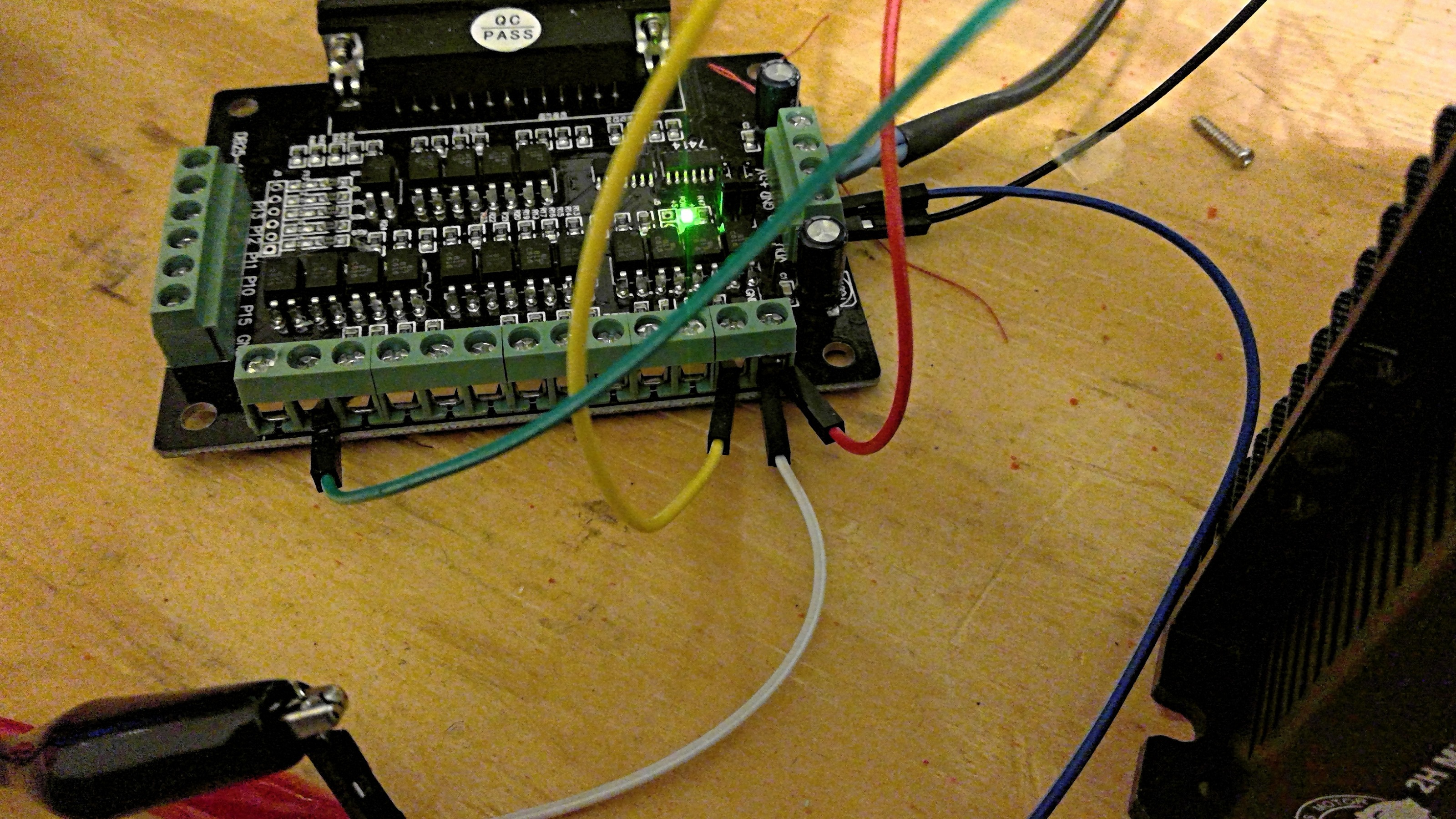
A.2. Wiring (you will normally find attached a picture of it):
Pul + / dir + / enbl + are bridged together with the +5 V on the break out board
Pul - is wired on the pin 2 on the breakout board
Dir - is wired on the pin 3 on the breakout board
Enbl - is wired on the pin 17 on the breakout board
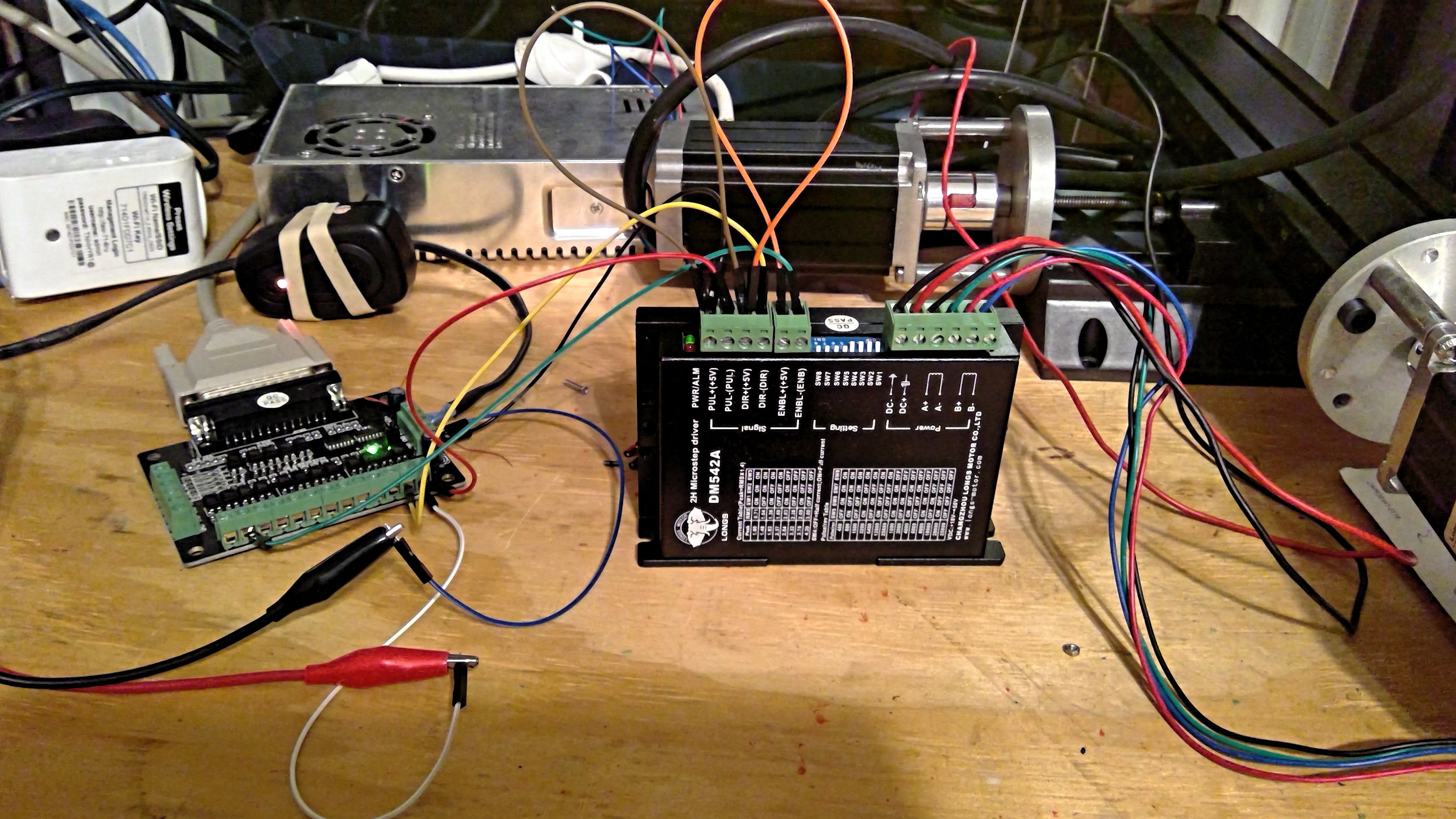
A.3. Drive :
the deep switches are set up for a 400 Pulse/rev and 1 A for the peak
B. What is happening
B.1 I can enable or desable the motor.
Enable : I have 5.2 V on the pin 17 , the green light on the drive up and the shaft of the motor locked.
Desable : I have 1. 5 V on the pin 17, the red light on the drive up and the shaft of the motor free.
B.2 Direction
If I hit the X- on linux CNC I have 5.2 V on the pin 3
If I hit the X+ on linux CNC I have 1.5 V on the pin 3
B.3 Direction
If I unwire Pul + / dir + / enbl + then I will have
If I hit the X- on linux CNC I have 5.2 V on the pin 3
If I hit the X+ on linux CNC I have 0.3 V on the pin 3 (LIKE IN THE VIDEO)
B.4 Step ( I purchased an osciloscope to check but I have so far couldn't set it properly to find a signal)
Set up for the oscilo : 5V / DC / 0.5 ms (it comes from the video), the wiring is the black on the ground on the break out board) and the red on the pin 2) but I get nothing.
C. Configuration on Linux CNC
I followed the configuration given in the video. I even did the Parport which is 0x378.
Can you please tell me if you see anything wrong ?
The only idea I have is about the wiring as I have 1.5 V instead of 0.3 V like in the video.
Thanks for your help

I purchased a set of 4 DM542A drives and a break out board DB25-1205 but I still cannot have a motor running.
A. materiel
I will break down every informations I have hoping someone will dig out the problem.
Here is the videos I followed to do the wiring and configurations :
A.1.The computer I use is a Dell optiplex 745
the jitter I found on the internet is the first value and the one given by LinuxCNC is the second
Max interval (1,0 ms thread) 1064158 / 1039109
Max jitter (1,0 ms thread) 64918 / 42229
Max interval (25 micro second) 49610 / 45275
Max interval (25 micro second) 24629 / 20353
A.2. Wiring (you will normally find attached a picture of it):
Pul + / dir + / enbl + are bridged together with the +5 V on the break out board
Pul - is wired on the pin 2 on the breakout board
Dir - is wired on the pin 3 on the breakout board
Enbl - is wired on the pin 17 on the breakout board
A.3. Drive :
the deep switches are set up for a 400 Pulse/rev and 1 A for the peak
B. What is happening
B.1 I can enable or desable the motor.
Enable : I have 5.2 V on the pin 17 , the green light on the drive up and the shaft of the motor locked.
Desable : I have 1. 5 V on the pin 17, the red light on the drive up and the shaft of the motor free.
B.2 Direction
If I hit the X- on linux CNC I have 5.2 V on the pin 3
If I hit the X+ on linux CNC I have 1.5 V on the pin 3
B.3 Direction
If I unwire Pul + / dir + / enbl + then I will have
If I hit the X- on linux CNC I have 5.2 V on the pin 3
If I hit the X+ on linux CNC I have 0.3 V on the pin 3 (LIKE IN THE VIDEO)
B.4 Step ( I purchased an osciloscope to check but I have so far couldn't set it properly to find a signal)
Set up for the oscilo : 5V / DC / 0.5 ms (it comes from the video), the wiring is the black on the ground on the break out board) and the red on the pin 2) but I get nothing.
C. Configuration on Linux CNC
I followed the configuration given in the video. I even did the Parport which is 0x378.
Can you please tell me if you see anything wrong ?
The only idea I have is about the wiring as I have 1.5 V instead of 0.3 V like in the video.
Thanks for your help
Last edit: 18 Mar 2018 03:02 by vfontaine.
Please Log in or Create an account to join the conversation.
- rodw
-

- Away
- Platinum Member
-

Less
More
- Posts: 12054
- Thank you received: 4114
18 Mar 2018 08:55 #107484
by rodw
Replied by rodw on topic DM542A / DB25-1205 Probable wiring issue
I use these exact same drives but I have never used the breakout board that came with them becasue I use Mesa hardware. I use 20x microstepping and run them at up to 21 metres per minute.
You say you can enable and disable the drives but you don't say how.
For now, I suggest you unplug the enable connections becasue turning this signal on will actually disable the stepper and you don't want that when setting up your system.
There are two things to look for in your INI file.
First are the steplen and step space settings. If they are too short it won't work. try > 5000
Second is that if you have the velocities or number of steps per device unit (inches or mm) wrong, the motor could be moving so slowly you might not notice. Thats what happened to me on my first try.
If you attach your ini nad hal files somebody might have some better ideas.
Please Log in or Create an account to join the conversation.
- andypugh
-

- Offline
- Moderator
-

Less
More
- Posts: 19886
- Thank you received: 4645
19 Mar 2018 13:26 #107542
by andypugh
Replied by andypugh on topic DM542A / DB25-1205 Probable wiring issue
If you have +5 to STEP+ and BoB to STEP- then the BoB is sinking current, and you will need to invert the step polarity in Stepconf (or by editing the HAL file).
Also, make the step length at least 5000nS (5 uS)
Also, make the step length at least 5000nS (5 uS)
Please Log in or Create an account to join the conversation.
- tommylight
-

- Away
- Moderator
-
Less
More
- Posts: 21764
- Thank you received: 7438
20 Mar 2018 02:20 #107579
by tommylight
Replied by tommylight on topic DM542A / DB25-1205 Probable wiring issue
The BOB in the picture ( not the video) uses some very slow optocouplers so you will have to manually edit the INI file and set the base thread to at least 100.000 or they will not work.
They put out the ugliest square wave i have ever seen, so not square by a long shot.
You could wire the drives directly, i did.
They put out the ugliest square wave i have ever seen, so not square by a long shot.
You could wire the drives directly, i did.
Please Log in or Create an account to join the conversation.
- vfontaine
- Offline
- New Member
-
Less
More
- Posts: 3
- Thank you received: 0
20 Mar 2018 15:59 #107621
by vfontaine
Replied by vfontaine on topic DM542A / DB25-1205 Probable wiring issue
Ok, I will try it this weekend and let you know the outcome. Thanks
Please Log in or Create an account to join the conversation.
- vfontaine
- Offline
- New Member
-
Less
More
- Posts: 3
- Thank you received: 0
25 Mar 2018 15:30 - 25 Mar 2018 15:33 #107819
by vfontaine
Replied by vfontaine on topic DM542A / DB25-1205 Probable wiring issue
Hello everybody.
Motor is running. the main problems as you mentionned were the step time and step space not high enough. The maximum velocity was also too low.
My actual issue is the speed of the motor. It is still slow.
I played with different parameters but don't get the expected result :
-I modified the step time and step space from 50 to 100 000 both and found out that the least bad setting is around 5000.
- I played a lot with the parameters of the axis X itself (microstepping, leadscrew pitch , etc...) but did not get much better result.
- I changed the Base period and servo period parameters in the INI file. (INI and HAL files are attached)
- I wirred the pin 2 and 3 of the parallel port to the pul- and dir- on the drive. I can only go negative direction and the speed didn't change.
- I played with the switches on the drive. did nothing about the speed.
Any ideas ?
Last edit: 25 Mar 2018 15:33 by vfontaine.
Please Log in or Create an account to join the conversation.
Time to create page: 0.215 seconds