encoder not working
- PCW
-

- Away
- Moderator
-

Less
More
- Posts: 17996
- Thank you received: 5282
06 Feb 2019 17:37 - 06 Feb 2019 17:38 #125834
by PCW
Replied by PCW on topic encoder not working
If they are differential encoders, check that you have both positive and negative voltage across A to /A and B to /B and never a voltage less than +2 or -2V between the pairs (while teasing the encoder to get all output states)
(there are 24 ways to swap the A,/A/B,/B wires and only some work...)
(there are 24 ways to swap the A,/A/B,/B wires and only some work...)
Last edit: 06 Feb 2019 17:38 by PCW.
Please Log in or Create an account to join the conversation.
- hatch789
-

- Offline
- Premium Member
-

Less
More
- Posts: 143
- Thank you received: 0
06 Feb 2019 18:55 #125846
by hatch789
Replied by hatch789 on topic encoder not working
Thanks Todd and PCW ... I did check the wires and it seems they are correct as the phases are in the right order when comparing between the 2 encoders moving at the same speed. Reversing changes the phases but this too seems correct and matches between the working and non-working one. So on the o-scope they both look the same.
Peter to your point I only have: G, W, R, B, Shld (so 5 wires)
The shield acts as A/ and B/ so it's a shared (ground of sorts) and I guess I can try swapping the G & W wires around to see if that makes a difference but really that's all that could be mis-soldered inside.
When you speak of getting neg & pos voltages across the pairs I will have to scope them again but it seems that moving the encoder left and right (on both of my units) only produces a shifted signal, not an inverted voltage signal. I will look more carefully tonight.
Please Log in or Create an account to join the conversation.
- PCW
-
- Away
- Moderator
-
Less
More
- Posts: 17996
- Thank you received: 5282
06 Feb 2019 19:00 #125848
by PCW
Replied by PCW on topic encoder not working
When I said measure across the pairs, I assumed it was differential
If you only have 5 wires, you have single ended encoders.
Note that these should wired to the 7I48 A,B,I inputs and the /A. /B, /I inputs on the 7i48
should be left open, and the 7I48 jumpered for TTL (single ended) mode
If you only have 5 wires, you have single ended encoders.
Note that these should wired to the 7I48 A,B,I inputs and the /A. /B, /I inputs on the 7i48
should be left open, and the 7I48 jumpered for TTL (single ended) mode
Please Log in or Create an account to join the conversation.
- Todd Zuercher
-

- Away
- Platinum Member
-

Less
More
- Posts: 4764
- Thank you received: 1464
06 Feb 2019 19:16 #125850
by Todd Zuercher
Replied by Todd Zuercher on topic encoder not working
If you only have 4 wires + a shield the encoders are not differential, so you wouldn't use /A or /B connectors. Normally there will be a minimum of a 5v wire, a ground wire, and A, B. Optionally there also could be /A, /B, I, and /I.
Please Log in or Create an account to join the conversation.
- hatch789
-
- Offline
- Premium Member
-
Less
More
- Posts: 143
- Thank you received: 0
06 Feb 2019 20:42 - 06 Feb 2019 20:50 #125865
by hatch789
Replied by hatch789 on topic encoder not working
My little encoders I got are just cheap encoders without an index. www.amazon.com/gp/product/B00UTIFCVA/ref...00_s00?ie=UTF8&psc=1
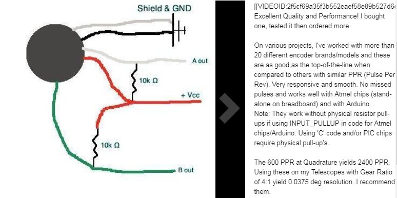
So green is A, white is B ...red and black for the 5v+ and Grnd
Then I assumed shield was used as a shared /A and /B
This is working on the O-Scope this way but I can't find clear information on the TTL stuff with the 7i48 card. So maybe I have it wrong. If the shield is not a shared return for A & B do I just not connect the shield to anything?
A user shared this image but it didn't make sense to me before. Now with what your saying about TTL maybe it is what I need to do. Do the 7i48's have these pull-up resistors (10k ohm) built in? The document only had mention 1 time of pull-up resistors but not what value they were.
So maybe I wire Green to pin1, black & shield to pin3, white to pin4, red to pin6
That's only 6 connections on the 7i48 and made no sense to me but if TTL mode is used like that (single ended?) then that makes sense. I just need to know if I need 10k resistors or not like the image below.
Attachments:
Last edit: 06 Feb 2019 20:50 by hatch789.
Please Log in or Create an account to join the conversation.
- PCW
-
- Away
- Moderator
-
Less
More
- Posts: 17996
- Thank you received: 5282
06 Feb 2019 20:50 #125868
by PCW
Replied by PCW on topic encoder not working
For TTL mode:
1. You need the 7I48 jumpered for TTL mode
2. The /A and /B inputs on the 7I48 must be left open (unconnected)
3. Leave the shield unconnected at the 7I48 end
1. You need the 7I48 jumpered for TTL mode
2. The /A and /B inputs on the 7I48 must be left open (unconnected)
3. Leave the shield unconnected at the 7I48 end
Please Log in or Create an account to join the conversation.
- hatch789
-
- Offline
- Premium Member
-
Less
More
- Posts: 143
- Thank you received: 0
06 Feb 2019 21:37 #125879
by hatch789
Replied by hatch789 on topic encoder not working
Peter did you see the diagram and extra info I added to my message before you replied? My edit and your reply were both 20:50 timestamps so you might not have seen that in time.
Please Log in or Create an account to join the conversation.
- PCW
-
- Away
- Moderator
-
Less
More
- Posts: 17996
- Thank you received: 5282
06 Feb 2019 21:59 #125881
by PCW
Replied by PCW on topic encoder not working
No pullups are needed (there are 2K pullups built into the 7I48)
but the encoder inputs must be jumpered for TTL mode:
7i48 manual page 2
but the encoder inputs must be jumpered for TTL mode:
7i48 manual page 2
Please Log in or Create an account to join the conversation.
- Ianw
- Offline
- New Member
-

Less
More
- Posts: 12
- Thank you received: 0
07 Feb 2019 18:32 #125939
by Ianw
Replied by Ianw on topic encoder not working
Hi Todd, My encoder disk has 60 slots. I have attached a couple of screen grabs
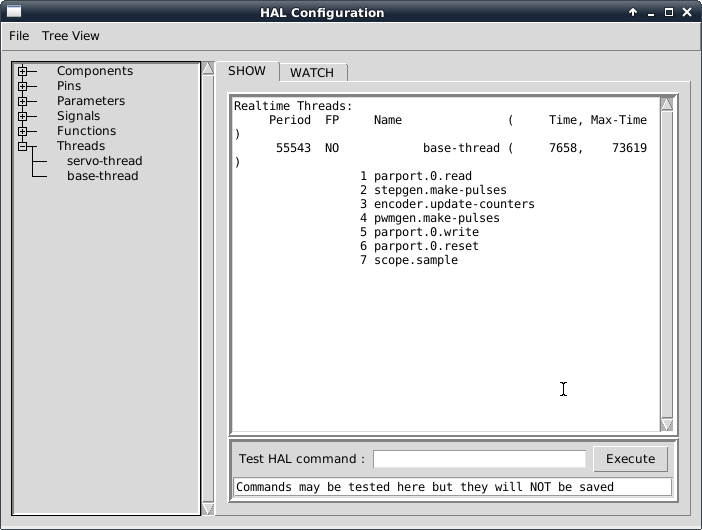

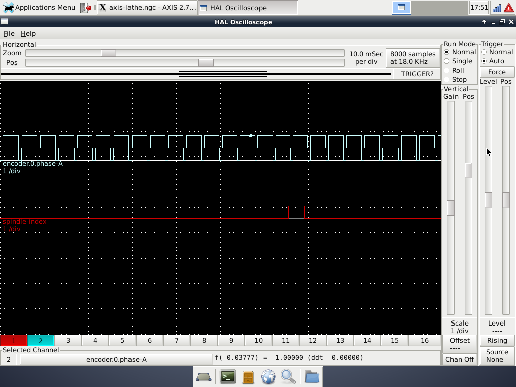 which I hope will give you a better idea of what's happening. The halscope one was taken with the lathe running at about 240rpm. Up to around 300rpm, I get a screen indication of spindle speed which is pretty sound but, above that it starts to get flaky and at around 36rpm, just gives up and goes back to zero. I tried a bit of simulated screwcutting with it last night and, up to around 300rpm it seemed to behave OK and, altering the spindle speed, the tool seemed to track the changes but, again, above 350 or 360, it just stopped moving. I suspect it may be the optos that have some kind of delay in there if other people have things working ok, I'm going to try to trace the circuit shortly, otherwise I'll need to try to figure out what kind of circuit is needed to interface plain slotted optos..
Attachments:
Please Log in or Create an account to join the conversation.
- Ianw
- Offline
- New Member
-
Less
More
- Posts: 12
- Thank you received: 0
07 Feb 2019 20:20 #125951
by Ianw
Replied by Ianw on topic encoder not working
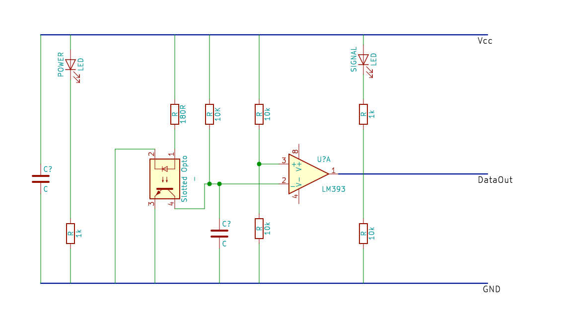
I have traced the circuit of the cheap optical slot sensors I am using - the only thing I couldn't identify was the values of the two capacitors. To my very limited eye, there doesn't seem to be anything which would slow down the signal going into the parallel port...
Attachments:
Please Log in or Create an account to join the conversation.
Time to create page: 0.334 seconds