Servo adjust with encoder feedback
- chris@cnc
- Offline
- Platinum Member
-

Less
More
- Posts: 529
- Thank you received: 140
09 Oct 2019 19:26 #147589
by chris@cnc
Servo adjust with encoder feedback was created by chris@cnc
Hi,
I'm trying to connect the feedback from the encoder to a 7i76e. Was not easy but now it works more or less. The problem now is after arrived servo the final position he reverses. I'm programming X200. -> Servo drives with 2m / min to about 200.5 and then slowly back to 200mm. Depends also on the speed and over 4m / min is alarm Joint following error. He is right, too.
The scaling fits and with or without encoder the position is correct at the end. When I turn on PID and I it gets a bit better until the servo begins to vibrate. If I increase the gain of the servo, it is better just not good. Is there something else with which I can adjust on servo and control?
Does anyone have an example configuration of a servo with encoder feedback or had similar problems?
Thanks Christian
Please Log in or Create an account to join the conversation.
- tommylight
-

- Offline
- Moderator
-

Less
More
- Posts: 21764
- Thank you received: 7438
09 Oct 2019 19:40 #147591
by tommylight
Replied by tommylight on topic Servo adjust with encoder feedback
That is due to tuning, overshooting it's position.
Have a read through this:
forum.linuxcnc.org/10-advanced-configura...ning-detailed-how-to
Have a read through this:
forum.linuxcnc.org/10-advanced-configura...ning-detailed-how-to
Please Log in or Create an account to join the conversation.
- chris@cnc
- Offline
- Platinum Member
-
Less
More
- Posts: 529
- Thank you received: 140
11 Oct 2019 17:54 - 11 Oct 2019 17:57 #147718
by chris@cnc
Replied by chris@cnc on topic Servo adjust with encoder feedback
Hi,
thanks for the guide but it was more than one problem. I found a parameter in the amplifier: Max encoder scale output. I have set it now equal to the input signal and then started to test with P0. Sometimes luck is with the stupid ones. It runs without vibration noise and overshoot.")
Can one still tell me what the max frequency is for the encoder output signal? At the moment I have a resolution of 5μm and measure almost 40Hz at 12m / min rapid feed. The signal is differential A, B. I've read something from 40 Hz but do not know where ...
And last question. My dream would be a homing with Z-phase and parameter shift. This would make it easier to adjust the gantry drive. Otherwise I have to push the reference cam and that is not so accurate.
Does anyone have an example hal and ini section?
Thanks Christian
thanks for the guide but it was more than one problem. I found a parameter in the amplifier: Max encoder scale output. I have set it now equal to the input signal and then started to test with P0. Sometimes luck is with the stupid ones. It runs without vibration noise and overshoot.
Can one still tell me what the max frequency is for the encoder output signal? At the moment I have a resolution of 5μm and measure almost 40Hz at 12m / min rapid feed. The signal is differential A, B. I've read something from 40 Hz but do not know where ...
And last question. My dream would be a homing with Z-phase and parameter shift. This would make it easier to adjust the gantry drive. Otherwise I have to push the reference cam and that is not so accurate.
Does anyone have an example hal and ini section?
Thanks Christian
Last edit: 11 Oct 2019 17:57 by chris@cnc.
Please Log in or Create an account to join the conversation.
- Hakan
- Offline
- Platinum Member
-
Less
More
- Posts: 1317
- Thank you received: 453
12 Oct 2019 13:28 #147736
by Hakan
Replied by Hakan on topic Servo adjust with encoder feedback
You are using the spindle encoder on the 7i76e aka high speed encoder? That one handles 10 MHz.
Don't know about the MPG-encoder interface if that's what you are using.
Don't know about the MPG-encoder interface if that's what you are using.
Please Log in or Create an account to join the conversation.
- chris@cnc
- Offline
- Platinum Member
-
Less
More
- Posts: 529
- Thank you received: 140
12 Oct 2019 19:56 #147754
by chris@cnc
Replied by chris@cnc on topic Servo adjust with encoder feedback
I use the input TB3 pin 7-14 on the 7i76e and tried it on the 7i85s on TB3 1-8. Works well, I am still in the test run. Only drive from X0 -> X200 in rapid traverse and with F1000 m / min back and measure how well the position holds. After about 10-15 minutes, everything is still in tolerance. At 40HZ nothing is lost from the encoder feedback. It would be nice to know what the card can do. I want to prevent a bad surprise later in the gantry operation. Any idea for homing. I have found in the HAL pin joint.0.motor.offset. Unfortunately nothing in the manual. Has one already played around with it?
Please Log in or Create an account to join the conversation.
- tommylight
-
- Offline
- Moderator
-
Less
More
- Posts: 21764
- Thank you received: 7438
12 Oct 2019 21:36 #147758
by tommylight
Replied by tommylight on topic Servo adjust with encoder feedback
Where do you keep getting that "40HZ" ???
If you sneeze near an encoder, chances are it will count faster than that.
Do you mean 40kHz ? That is 40000Hz. That is still very low for what the encoder input on the 7i76E ( spindle encoder ) can handle, but if you are using MPG encoder feedback, that is to much.
Can you please share more info on what you are using and how it is wired/connected ?
Please Log in or Create an account to join the conversation.
- chris@cnc
- Offline
- Platinum Member
-
Less
More
- Posts: 529
- Thank you received: 140
13 Oct 2019 13:17 - 13 Oct 2019 13:19 #147816
by chris@cnc
Replied by chris@cnc on topic Servo adjust with encoder feedback
Hello Tommy,
Of course you are right there are no 40HZ in any case. It 40KHZ
My scaling is: One pulse is 5μ and one motor turn = 5mm. If I turn the servo, the control changes in 5μ steps.
Connection are as follows:
Step + Dir from 7i76e to Amplifier (Delta ASD-B2) =>
Power from the amplifier to the servo (Delta ECMA C20604) =>
Feedback (incremental) from the servo encoder to the amplifier =>
and in the end: feedback from the amplifier to the input encoder on tb3 7i785s. The signal is a difference signal with A, B and Z phase
I have measured once with the hal scope but unfortunately I can read anything on it. First image is at 500mm / min feed and the second with 1m / min. Maybe you can explain that.
Then I took my scope and simply measured between A and / A. Are 24V with a period of 49,6μs at 12m / min rapid feed. 3rd picture. On the top right you can see delta t = 49,6μs
Calculated I have now 1 / 0,00005s = 20000HZ * 2 (A and B phase) = 40KHZ. My mistake I forgot the K
I hope that my idea is not so bad ...
An idea what and how to start with the Z phase?
Last edit: 13 Oct 2019 13:19 by chris@cnc.
Please Log in or Create an account to join the conversation.
- PCW
-

- Away
- Moderator
-
Less
More
- Posts: 17996
- Thank you received: 5283
13 Oct 2019 13:40 #147818
by PCW
Replied by PCW on topic Servo adjust with encoder feedback
24V is _way_ too large a signal for a 7I76E or 7I85S encoder input
Both cards expect 5V signals
Both cards expect 5V signals
Please Log in or Create an account to join the conversation.
- chris@cnc
- Offline
- Platinum Member
-
Less
More
- Posts: 529
- Thank you received: 140
13 Oct 2019 14:44 #147819
by chris@cnc
Replied by chris@cnc on topic Servo adjust with encoder feedback
Ohhh
This is snippet from the manual. And that's exactly how the cables are. Where does the power come from?
+5V and GND are not connect.
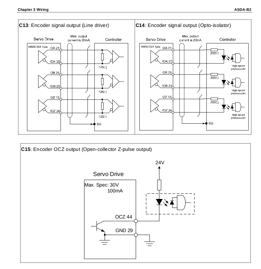
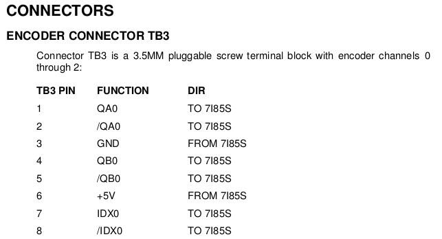
This is snippet from the manual. And that's exactly how the cables are. Where does the power come from?
+5V and GND are not connect.
Please Log in or Create an account to join the conversation.
- PCW
-
- Away
- Moderator
-
Less
More
- Posts: 17996
- Thank you received: 5283
13 Oct 2019 14:58 #147820
by PCW
Replied by PCW on topic Servo adjust with encoder feedback
OK those _should be_ 5V signals
no power is needed
(the OCZ signal is not used)
no power is needed
(the OCZ signal is not used)
Please Log in or Create an account to join the conversation.
Time to create page: 0.125 seconds