6i25 + 7i85 - BISS-C, hm2dpll timing
- rumking
- Offline
- New Member
-

Less
More
- Posts: 18
- Thank you received: 1
13 Jan 2022 08:32 #231642
by rumking
6i25 + 7i85 - BISS-C, hm2dpll timing was created by rumking
Hi guys,
I am trying to get working a BISS-C encoder on 6i25+7i85 combo. I created a bitfile myself, which looks like this:
I have the 7i85 on P2 of the 6i25, I connected the encoder to the SERIAL 4 of the 7i85. The encoder status led shows, that the encoder gets the MA clock, but the data transmission fails. Here is stdout after launching the machine.
I have the DPLL timer in the HAL file of the machine configured as follows.
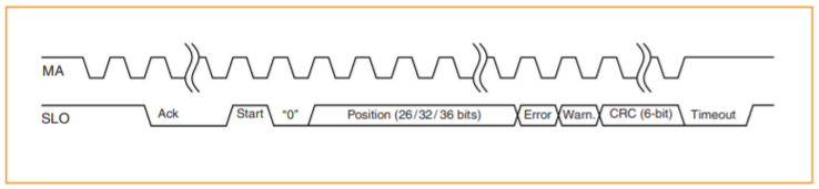
The encoder is an EVOLUTE™ RTLA50-S absolute optical encoder with following data format (46b total, position size is 36b).
I think I configured the DPLL timer correctly (biss frequency is 500kHz, data transfer of ~50b), so 200us of the DPLL timer should be more than enough. The dpll.phase-error-us does not exceed +-5us.
I did not touch any other parameters of the DPLL timer, however the default value of dpll.prescale should be 1, but in halmeter dpll.prescale shows value of 16.
Could you please help me, where am I making a mistake?
Vaclav, Czech Republic
I am trying to get working a BISS-C encoder on 6i25+7i85 combo. I created a bitfile myself, which looks like this:
sudo mesaflash --device 6i25 --readhmid
Configuration Name: HOSTMOT2

General configuration information:

  BoardName : MESA6I25
  FPGA Size: 9 KGates
  FPGA Pins: 144
  Number of IO Ports: 2
  Width of one I/O port: 17
  Clock Low frequency: 66.6667 MHz
  Clock High frequency: 200.0000 MHz
  IDROM Type: 3
  Instance Stride 0: 4
  Instance Stride 1: 64
  Register Stride 0: 256
  Register Stride 1: 256

Modules in configuration:

  Module: DPLL
  There are 1 of DPLL in configuration
  Version: 0
  Registers: 7
  BaseAddress: 7000
  ClockFrequency: 66.667 MHz
  Register Stride: 256 bytes
  Instance Stride: 4 bytes

  Module: WatchDog
  There are 1 of WatchDog in configuration
  Version: 0
  Registers: 3
  BaseAddress: 0C00
  ClockFrequency: 66.667 MHz
  Register Stride: 256 bytes
  Instance Stride: 4 bytes

  Module: IOPort
  There are 2 of IOPort in configuration
  Version: 0
  Registers: 5
  BaseAddress: 1000
  ClockFrequency: 66.667 MHz
  Register Stride: 256 bytes
  Instance Stride: 4 bytes

  Module: MuxedQCount
  There are 6 of MuxedQCount in configuration
  Version: 4
  Registers: 5
  BaseAddress: 3600
  ClockFrequency: 66.667 MHz
  Register Stride: 256 bytes
  Instance Stride: 4 bytes

  Module: MuxedQCountSel
  There are 1 of MuxedQCountSel in configuration
  Version: 0
  Registers: 0
  BaseAddress: 0000
  ClockFrequency: 66.667 MHz
  Register Stride: 256 bytes
  Instance Stride: 4 bytes

  Module: SSerial
  There are 1 of SSerial in configuration
  Version: 0
  Registers: 6
  BaseAddress: 5B00
  ClockFrequency: 66.667 MHz
  Register Stride: 256 bytes
  Instance Stride: 64 bytes

  Module: StepGen
  There are 5 of StepGen in configuration
  Version: 2
  Registers: 10
  BaseAddress: 2000
  ClockFrequency: 66.667 MHz
  Register Stride: 256 bytes
  Instance Stride: 4 bytes

  Module: LED
  There are 1 of LED in configuration
  Version: 0
  Registers: 1
  BaseAddress: 0200
  ClockFrequency: 66.667 MHz
  Register Stride: 256 bytes
  Instance Stride: 4 bytes

  Module: BISS
  There are 1 of BISS in configuration
  Version: 0
  Registers: 4
  BaseAddress: 4A00
  ClockFrequency: 200.000 MHz
  Register Stride: 256 bytes
  Instance Stride: 4 bytes

Configuration pin-out:

IO Connections for P3
Pin#  I/O   Pri. func    Sec. func       Chan      Pin func        Pin Dir

 1      0   IOPort       StepGen          0        Dir/Table2      (Out)
14      1   IOPort       StepGen          0        Step/Table1     (Out)
 2      2   IOPort       StepGen          1        Dir/Table2      (Out)
15      3   IOPort       StepGen          1        Step/Table1     (Out)
 3      4   IOPort       StepGen          2        Dir/Table2      (Out)
16      5   IOPort       StepGen          2        Step/Table1     (Out)
 4      6   IOPort       StepGen          3        Dir/Table2      (Out)
17      7   IOPort       StepGen          3        Step/Table1     (Out)
 5      8   IOPort       StepGen          4        Dir/Table2      (Out)
 6      9   IOPort       StepGen          4        Step/Table1     (Out)
 7     10   IOPort       SSerial          0        TXData0         (Out)
 8     11   IOPort       SSerial          0        RXData0         (In)
 9     12   IOPort       SSerial          0        TXData1         (Out)
10     13   IOPort       SSerial          0        RXData1         (In)
11     14   IOPort       MuxedQCount      0        MuxQ-IDX        (In)
12     15   IOPort       MuxedQCount      0        MuxQ-B          (In)
13     16   IOPort       MuxedQCount      0        MuxQ-A          (In)

IO Connections for P2
Pin#  I/O   Pri. func    Sec. func       Chan      Pin func        Pin Dir

 1     17   IOPort       BISS             0        Din             (In)
14     18   IOPort       BISS             0        Clk             (Out)
 2     19   IOPort       SSerial          0        RXData5         (In)
15     20   IOPort       SSerial          0        TXData5         (Out)
 3     21   IOPort       SSerial          0        RXData4         (In)
16     22   IOPort       SSerial          0        TXData4         (Out)
 4     23   IOPort       SSerial          0        RXData3         (In)
17     24   IOPort       SSerial          0        TXData3         (Out)
 5     25   IOPort       SSerial          0        RXData2         (In)
 6     26   IOPort       SSerial          0        TXData2         (Out)
 7     27   IOPort       MuxedQCountSel   2        MuxSel0         (Out)
 8     28   IOPort       MuxedQCount      1        MuxQ-A          (In)
 9     29   IOPort       MuxedQCount      1        MuxQ-B          (In)
10     30   IOPort       MuxedQCount      1        MuxQ-IDX        (In)
11     31   IOPort       MuxedQCount      2        MuxQ-A          (In)
12     32   IOPort       MuxedQCount      2        MuxQ-B          (In)
13     33   IOPort       MuxedQCount      2        MuxQ-IDX        (In)
I have the 7i85 on P2 of the 6i25, I connected the encoder to the SERIAL 4 of the 7i85. The encoder status led shows, that the encoder gets the MA clock, but the data transmission fails. Here is stdout after launching the machine.
LINUXCNC - 2.8.2
Machine configuration directory is '/home/biomech/linuxcnc/configs/my_LinuxCNC_machine_biss'
Machine configuration file is 'my_LinuxCNC_machine.ini'
Starting LinuxCNC...
Found file(REL): ./my_LinuxCNC_machine.hal
Note: Using POSIX realtime
hm2: loading Mesa HostMot2 driver version 0.15
hm2_pci: loading Mesa AnyIO HostMot2 driver version 0.7
hm2_pci: discovered 6i25 at 0000:02:00.0
hm2/hm2_6i25.0: Low Level init 0.15
hm2/hm2_6i25.0: Smart Serial Firmware Version 43
hm2/hm2_6i25.0: 34 I/O Pins used:
hm2/hm2_6i25.0:     IO Pin 000 (P3-01): IOPort
hm2/hm2_6i25.0:     IO Pin 001 (P3-14): IOPort
hm2/hm2_6i25.0:     IO Pin 002 (P3-02): IOPort
hm2/hm2_6i25.0:     IO Pin 003 (P3-15): IOPort
hm2/hm2_6i25.0:     IO Pin 004 (P3-03): IOPort
hm2/hm2_6i25.0:     IO Pin 005 (P3-16): IOPort
hm2/hm2_6i25.0:     IO Pin 006 (P3-04): IOPort
hm2/hm2_6i25.0:     IO Pin 007 (P3-17): IOPort
hm2/hm2_6i25.0:     IO Pin 008 (P3-05): IOPort
hm2/hm2_6i25.0:     IO Pin 009 (P3-06): IOPort
hm2/hm2_6i25.0:     IO Pin 010 (P3-07): IOPort
hm2/hm2_6i25.0:     IO Pin 011 (P3-08): IOPort
hm2/hm2_6i25.0:     IO Pin 012 (P3-09): IOPort
hm2/hm2_6i25.0:     IO Pin 013 (P3-10): IOPort
hm2/hm2_6i25.0:     IO Pin 014 (P3-11): IOPort
hm2/hm2_6i25.0:     IO Pin 015 (P3-12): IOPort
hm2/hm2_6i25.0:     IO Pin 016 (P3-13): IOPort
hm2/hm2_6i25.0:     IO Pin 017 (P2-01): BiSS Encoder #0, pin data (Input)
hm2/hm2_6i25.0:     IO Pin 018 (P2-14): BiSS Encoder #0, pin clock (Output)
hm2/hm2_6i25.0:     IO Pin 019 (P2-02): IOPort
hm2/hm2_6i25.0:     IO Pin 020 (P2-15): IOPort
hm2/hm2_6i25.0:     IO Pin 021 (P2-03): IOPort
hm2/hm2_6i25.0:     IO Pin 022 (P2-16): IOPort
hm2/hm2_6i25.0:     IO Pin 023 (P2-04): IOPort
hm2/hm2_6i25.0:     IO Pin 024 (P2-17): IOPort
hm2/hm2_6i25.0:     IO Pin 025 (P2-05): IOPort
hm2/hm2_6i25.0:     IO Pin 026 (P2-06): IOPort
hm2/hm2_6i25.0:     IO Pin 027 (P2-07): IOPort
hm2/hm2_6i25.0:     IO Pin 028 (P2-08): IOPort
hm2/hm2_6i25.0:     IO Pin 029 (P2-09): IOPort
hm2/hm2_6i25.0:     IO Pin 030 (P2-10): IOPort
hm2/hm2_6i25.0:     IO Pin 031 (P2-11): IOPort
hm2/hm2_6i25.0:     IO Pin 032 (P2-12): IOPort
hm2/hm2_6i25.0:     IO Pin 033 (P2-13): IOPort
hm2/hm2_6i25.0: registered
hm2_6i25.0: initialized AnyIO board at 0000:02:00.0
Found file(REL): ./custom.hal
hm2/hm2_6i25.0: BISS DDS set to 163
hm2/hm2_6i25.0: BISS Filter set to 63
note: MAXV     max: 1.000 units/sec 60.000 units/min
note: LJOG     max: 1.000 units/sec 60.000 units/min
note: LJOG default: 0.250 units/sec 15.000 units/min
waiting for s.joints<0>, s.kinematics_type<0>
waiting for s.joints<0>, s.kinematics_type<0>
note: jog_order='XYZ'
note: jog_invert=set([])
hm2/hm2_6i25.0: Data transmission not complete on channel hm2_6i25.0.biss.00 read. You  may need to change the timing of the hm2dpll timer. This warning  will not repeat

hm2/hm2_6i25.0: Data transmission not complete on channel hm2_6i25.0.biss.00 read. You  may need to change the timing of the hm2dpll timer. This warning  will not repeat
I have the DPLL timer in the HAL file of the machine configured as follows.
loadrt [KINS]KINEMATICS
loadrt [EMCMOT]EMCMOT servo_period_nsec=[EMCMOT]SERVO_PERIOD num_joints=[KINS]JOINTS
loadrt hostmot2
loadrt hm2_pci config="num_dplls=1 num_encoders=0 num_pwmgens=0 num_stepgens=0 sserial_port_0=00xxxx biss_chan_0=start%2pencoder%36eerror%1bwarning%1bcrc%6p"

addf motion-command-handler   servo-thread
addf motion-controller        servo-thread

addf hm2_6i25.0.read          servo-thread
addf hm2_6i25.0.write         servo-thread
setp hm2_6i25.0.watchdog.timeout_ns         5000000

setp hm2_6i25.0.dpll.01.timer-us -200
setp hm2_6i25.0.biss.00.timer-number 1

#  ---estop signals---

net estop-out     <=  iocontrol.0.user-enable-out
net estop-out     =>  iocontrol.0.emc-enable-in
The encoder is an EVOLUTE™ RTLA50-S absolute optical encoder with following data format (46b total, position size is 36b).
I think I configured the DPLL timer correctly (biss frequency is 500kHz, data transfer of ~50b), so 200us of the DPLL timer should be more than enough. The dpll.phase-error-us does not exceed +-5us.
I did not touch any other parameters of the DPLL timer, however the default value of dpll.prescale should be 1, but in halmeter dpll.prescale shows value of 16.
Could you please help me, where am I making a mistake?
Vaclav, Czech Republic
Attachments:
Please Log in or Create an account to join the conversation.
- tommylight
-

- Offline
- Moderator
-

Less
More
- Posts: 21658
- Thank you received: 7400
13 Jan 2022 11:08 #231650
by tommylight
Replied by tommylight on topic 6i25 + 7i85 - BISS-C, hm2dpll timing
Ahoj Vaclav,
Had the same "You may need to change the timing of the hm2dpll timer. This warning will not repeat" lately with a perfectly working machine after changing the PC, changed it again to an old Dell and everything works perfectly.
I did play with timings and stuff, did not help much.
The original PC was a Shuttle, old P4, worked for over 5 years till the power supply failed.
The second PC, the one causing issues was a Dell core2duo mini tower.
The third and currently working again Dell SFF core2duo.
5i25/7i77/7i74/7i70/7i71
So try another PC .
Please Log in or Create an account to join the conversation.
- PCW
-

- Offline
- Moderator
-
Less
More
- Posts: 17929
- Thank you received: 5253
13 Jan 2022 16:16 #231675
by PCW
Replied by PCW on topic 6i25 + 7i85 - BISS-C, hm2dpll timing
What servo thread rate are you running?
"Data Transmission not complete" means the RX logic was busy
when LInuxCNC attempted to read the data. which may mean
either a timing error or that no start bit was detected.
"Data Transmission not complete" means the RX logic was busy
when LInuxCNC attempted to read the data. which may mean
either a timing error or that no start bit was detected.
Please Log in or Create an account to join the conversation.
- rumking
- Offline
- New Member
-
Less
More
- Posts: 18
- Thank you received: 1
13 Jan 2022 18:32 #231692
by rumking
Replied by rumking on topic 6i25 + 7i85 - BISS-C, hm2dpll timing
Thank you for the suggestions. I am running 1kHz servo-thread.
I managed to get some data from the encoder. There was a flaw in my wiring and after adjusting the timing, it works, partially, atleast.
Setting the dpll.01.timer-us to -500 (minus 5 hundred microseconds) resolved the hm2/hm2_6i25.0: Data transmission not complete error.
However, now I am facing an issue (I am probably lacking some knowledge) with parsing the received bits. Could you help me with the configuration string of the BiSS channel?
The position of the ecoder is 26b (I initially thought it was 36b, but it is 26b, just to clarify).
I would like to parse all the data sent from the encoder. From what I was able to gather, the configuration of the BiSS channel should be (atleast I got most success with):
biss_chan_0=crc%6fwarning%1berror%1bencoder%26e"
This configuration results in:
- encoder position, which seems to be alright (maybe)
- both the error and warning bits are flipping, which they should not
- CRC with 4 bits flipping (which is what I expected) and 2 bits constantly FALSE
With the original configuration (adjusted to proper encoder position size of 26b)
biss_chan_0=start%2pencoder%36eerror%1bwarning%1bcrc%6p"
I get complete non-sense.
Could you help me with construction of the channel configuration string? Can you help me whether or not should I account for the start and "0" bits?
The start and "0" bits are not the first two (if I put the data in plain array of bits), because they are flipping.
I really appreciate your help.
Vaclav
Please Log in or Create an account to join the conversation.
- PCW
-
- Offline
- Moderator
-
Less
More
- Posts: 17929
- Thank you received: 5253
13 Jan 2022 23:27 - 13 Jan 2022 23:36 #231718
by PCW
Replied by PCW on topic 6i25 + 7i85 - BISS-C, hm2dpll timing
The BISS firmware starts acquiring data after the start bit, so the 0 would
be part of the data.
Note that inverted data (swapped data lines) would cause the start bit also to be acquired.
(and this would cause an apparent off by 2 error that your CRC shows)
I would check the first 2 bits to see if they make sense (make a string that captures them to individual bits)
I suspect that you may need to swap both the clock and data pairs (and account for the 0 bit)
Last edit: 13 Jan 2022 23:36 by PCW.
Please Log in or Create an account to join the conversation.
- rumking
- Offline
- New Member
-
Less
More
- Posts: 18
- Thank you received: 1
18 Jan 2022 09:31 #232243
by rumking
Replied by rumking on topic 6i25 + 7i85 - BISS-C, hm2dpll timing
Hi guys,
I got the Renishaw Evolute absolute BiSS-C optical encoder finally working, datasheet is below, these were the obstacles, maybe it will help someone else.
www.renishaw.com/media/pdf/en/75bdde2f02...88845912c86eba6e.pdf
As PCW suggested, swapping the pairs of lines was needed. I swapped only the DATA line, i.e. connected the 7i85 DATA+ to SLO- and DATA- to SLO+. I did not swap the CLK line, i.e. 7i85 CLK+ is connected to MA+ and CLK- to MA-.
Then, a proper configuration of the BiSS channel was needed. I have the 26b position variant of the encoder. With this configuration, everythig is working:
biss_chan_0=null%1bcrc%6fwarning%1berror%1bencoder%26e
Which means the null bit, 6b CRC, 1b waring, 1b error, 26b position. I configured the BiSS frequency to 2MHz and DPLL timer to 100us, running without issues.
setp hm2_6i25.0.dpll.01.timer-us -100
setp hm2_6i25.0.biss.00.timer-number 1
setp hm2_6i25.0.biss.00.frequency-khz 2000
Maybe one last question I have. Is it possible to check the CRC (natively) directly in HAL? Or do I need to develop some kind of RT component which could handle that?
Thank you once again.
Please Log in or Create an account to join the conversation.
Time to create page: 0.125 seconds