Help with vfd 0-10v wiring/conf
- mart154
- Offline
- New Member
-

Less
More
- Posts: 6
- Thank you received: 1
08 Apr 2022 16:26 #239679
by mart154
Help with vfd 0-10v wiring/conf was created by mart154
Hi,
you have probably had endless amount of these posts, but my google-fu has failed me. Help a total beginner!
Main characters in my problem: Chinese 6040 router, 1.5kW watercooled spindle with a built in vfd. Originally with usb controller replaced with chinese "5 axis breakout with relay" forum.linuxcnc.org/media/kunena/attachme...25994/5axisboard.jpg
Now, I got all the axes and limits/homing working, but I'm getting no joy with spindle control.
From the spindle side, I have four wires: "0-10V", "GND", "Spindle CW" and "10V" as i understand the "10V" is just 10V supply wire, so not needed for me.
Connected "0-10V" and "GND" to BOB-s pwm pins, and "Spindle CW" to Pin16.
Went through Stepcontrol wizard, set pin16 to "Spindle CW" and pin 1 to "Spindle PWM"
When I press the "make clocwise noise" button, I can see the frequency on the VFD changing, but no movement. Also the speed seems to be calibrated to 6000rpm, and I have no idea how to change that, even if it would work")
Please help an idiot!
Cheers,
Mart
you have probably had endless amount of these posts, but my google-fu has failed me. Help a total beginner!
Main characters in my problem: Chinese 6040 router, 1.5kW watercooled spindle with a built in vfd. Originally with usb controller replaced with chinese "5 axis breakout with relay" forum.linuxcnc.org/media/kunena/attachme...25994/5axisboard.jpg
Now, I got all the axes and limits/homing working, but I'm getting no joy with spindle control.
From the spindle side, I have four wires: "0-10V", "GND", "Spindle CW" and "10V" as i understand the "10V" is just 10V supply wire, so not needed for me.
Connected "0-10V" and "GND" to BOB-s pwm pins, and "Spindle CW" to Pin16.
Went through Stepcontrol wizard, set pin16 to "Spindle CW" and pin 1 to "Spindle PWM"
When I press the "make clocwise noise" button, I can see the frequency on the VFD changing, but no movement. Also the speed seems to be calibrated to 6000rpm, and I have no idea how to change that, even if it would work
Please help an idiot!
Cheers,
Mart
Please Log in or Create an account to join the conversation.
- tommylight
-

- Offline
- Moderator
-

Less
More
- Posts: 21658
- Thank you received: 7400
08 Apr 2022 20:48 #239697
by tommylight
Se the manual on how to set the VFD to "remote" control mode, and check the pins that need to be active for "run" mode.
Replied by tommylight on topic Help with vfd 0-10v wiring/conf
That usually means the VFD is in "local" control mode or the "run" pin is not active.When I press the "make clocwise noise" button, I can see the frequency on the VFD changing, but no movement.
Se the manual on how to set the VFD to "remote" control mode, and check the pins that need to be active for "run" mode.
Please Log in or Create an account to join the conversation.
- mart154
- Offline
- New Member
-
Less
More
- Posts: 6
- Thank you received: 1
09 Apr 2022 05:52 #239711
by mart154
Replied by mart154 on topic Help with vfd 0-10v wiring/conf
I just double checked. As far as my knowledge goes, I'm in "pc mode" what they call.
The "local" pot and start/stop buttons are disabled.
When I switch it over to the other (presumably "local") mode, then I can control the frequency manually and no freq change when commanded by the pc.
Thank you.
The "local" pot and start/stop buttons are disabled.
When I switch it over to the other (presumably "local") mode, then I can control the frequency manually and no freq change when commanded by the pc.
Thank you.
When I press the "make clocwise noise" button, I can see the frequency on the VFD changing, but no movement.
That usually means the VFD is in "local" control mode or the "run" pin is not active.
Se the manual on how to set the VFD to "remote" control mode, and check the pins that need to be active for "run" mode.
Please Log in or Create an account to join the conversation.
- mart154
- Offline
- New Member
-
Less
More
- Posts: 6
- Thank you received: 1
09 Apr 2022 08:27 - 09 Apr 2022 08:29 #239717
by mart154
Replied by mart154 on topic Help with vfd 0-10v wiring/conf
Just tried wiring the "FWD" pin with 10V feed through the relay "parport 17". Relay clicks, frequency on vfd display changes, but no spin. Tried inverting the pins in stepconf also, still nothing. 
Edit: when I set the vfd to "manual control mode" then no frequency change from PC, but manual pot starts to work. So everything indicates the vfd is in "remote control mode"
Edit: when I set the vfd to "manual control mode" then no frequency change from PC, but manual pot starts to work. So everything indicates the vfd is in "remote control mode"
Last edit: 09 Apr 2022 08:29 by mart154.
Please Log in or Create an account to join the conversation.
- Clive S
- Offline
- Platinum Member
-

Less
More
- Posts: 2204
- Thank you received: 486
09 Apr 2022 09:18 #239718
by Clive S
Replied by Clive S on topic Help with vfd 0-10v wiring/conf
Can you draw a simple sketch of how you are physically connecting the wires to the bob?
Also can you post the config files ie. ini and hal files from the config folder?
Do you have a link to the manual for the vfd? so that the parameters can be checked.
Also can you post the config files ie. ini and hal files from the config folder?
Do you have a link to the manual for the vfd? so that the parameters can be checked.
Please Log in or Create an account to join the conversation.
- mart154
- Offline
- New Member
-
Less
More
- Posts: 6
- Thank you received: 1
09 Apr 2022 10:44 #239723
by mart154
Replied by mart154 on topic Help with vfd 0-10v wiring/conf
Hi Clive,
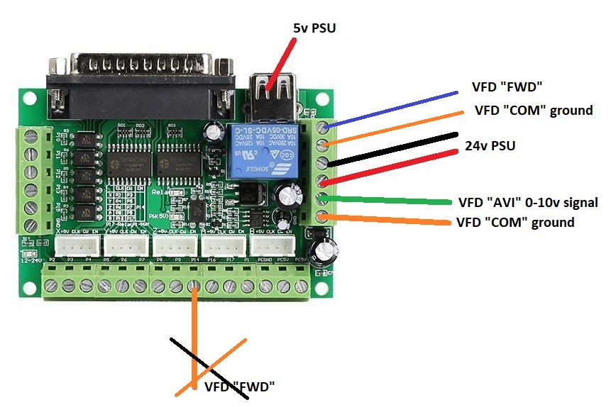
Little "schematic" and ini and hal files. Ini and hal are straight as they came from stepconfig. Have tried inverting the parport pins (1 and 14) through stepconfig.
Little "schematic" and ini and hal files. Ini and hal are straight as they came from stepconfig. Have tried inverting the parport pins (1 and 14) through stepconfig.
Please Log in or Create an account to join the conversation.
- Clive S
- Offline
- Platinum Member
-
Less
More
- Posts: 2204
- Thank you received: 486
09 Apr 2022 14:29 #239736
by Clive S
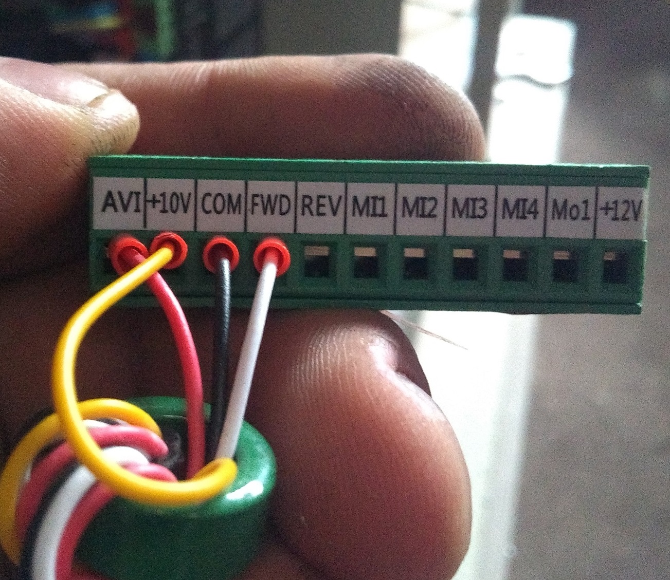
You have not said what VFD you are using. A pic of the terminal would help.
The VFD "FWD" (from the VFD) has to go to the relay (next to the 24V ps black wire) the other relay contact goes to the "DCM" in the VFD .
No spindle vfd wires connect to the bottom row of contacts on the BOB
Does the relay click when you command M3 S1000 (Or manually)
You might have to change this line in the hal file
net spindle-cw => parport.0.pin-14-out ..to
net spindle-cw => parport.0.pin-17-out
Replied by Clive S on topic Help with vfd 0-10v wiring/conf
Hi Clive,
Little "schematic" and ini and hal files. Ini and hal are straight as they came from stepconfig. Have tried inverting the parport pins (1 and 14) through stepconfig.
You have not said what VFD you are using. A pic of the terminal would help.
The VFD "FWD" (from the VFD) has to go to the relay (next to the 24V ps black wire) the other relay contact goes to the "DCM" in the VFD .
No spindle vfd wires connect to the bottom row of contacts on the BOB
Does the relay click when you command M3 S1000 (Or manually)
You might have to change this line in the hal file
net spindle-cw => parport.0.pin-14-out ..to
net spindle-cw => parport.0.pin-17-out
The following user(s) said Thank You: mart154
Please Log in or Create an account to join the conversation.
- mart154
- Offline
- New Member
-
Less
More
- Posts: 6
- Thank you received: 1
09 Apr 2022 15:34 #239745
by mart154
Replied by mart154 on topic Help with vfd 0-10v wiring/conf
Thank you Clive. That made total sense!Changed my HAL file as suggested and connected the FWD pin through the relay to COM.For completeness, it is one of these PRT-E1500W built in vfd's. Picture of the final wiring attached also.

Attachments:
Please Log in or Create an account to join the conversation.
- Clive S
- Offline
- Platinum Member
-
Less
More
- Posts: 2204
- Thank you received: 486
09 Apr 2022 16:54 - 09 Apr 2022 16:58 #239751
by Clive S
Replied by Clive S on topic Help with vfd 0-10v wiring/conf
Does that mean that it is working now.
If so that's great .
Edit: Forgot to mention that is is generally better to use a 5V PS connected to the terminals on the bottom row.
Ie .forget the usb
If so that's great .
Edit: Forgot to mention that is is generally better to use a 5V PS connected to the terminals on the bottom row.
Ie .forget the usb
Last edit: 09 Apr 2022 16:58 by Clive S.
Please Log in or Create an account to join the conversation.
- mart154
- Offline
- New Member
-
Less
More
- Posts: 6
- Thank you received: 1
09 Apr 2022 17:39 #239759
by mart154
Replied by mart154 on topic Help with vfd 0-10v wiring/conf
Yes, got it to work nicely. Thank you. Usb is actually ditched already. I just didn't mention it to avoid more confusion.
The following user(s) said Thank You: Clive S
Please Log in or Create an account to join the conversation.
Time to create page: 0.355 seconds