7i96S Basic Switch Wiring confirmation
- aikiaviator
- Offline
- Senior Member
-

Less
More
- Posts: 44
- Thank you received: 7
27 Nov 2024 04:25 #315339
by aikiaviator
7i96S Basic Switch Wiring confirmation was created by aikiaviator
Hi all, I know this has been aske before, however, there does not appear to be a simple visual on it. So thought I would confirm.
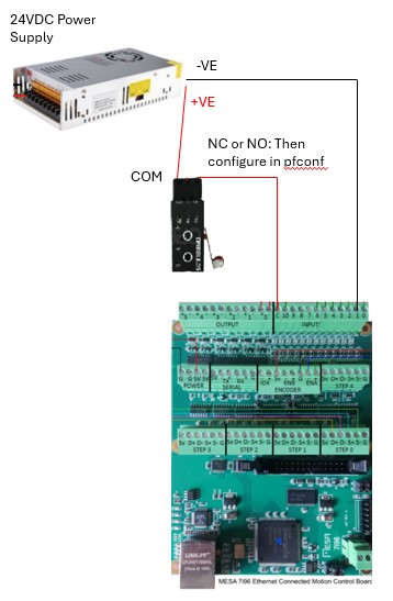
I am trying to set up limit switches. I would like to first test config on single switch. I believe that the best way is to wire a 24V power Supply +ve to the switch, then switch to the boards input Common. Then Wire 24V -ve to Input #. (Ref: Image attached.) Is this correct or should it be switch interrupting -ve side pathway?
I believe that once tested as confirmed I can run a single series based set of switches to use for X, Y and Z limit switches. Correct?
Thanks all.
https://www.dropbox.com/scl/fi/17swjx7ir9ssolq4dqoa8/Swtch-Wiring.jpg?rlkey=lulbgk3lvoq6ppejl3btlih2e&dl=0
Attachments:
Please Log in or Create an account to join the conversation.
- aikiaviator
- Offline
- Senior Member
-

Less
More
- Posts: 44
- Thank you received: 7
28 Nov 2024 06:35 #315439
by aikiaviator
Replied by aikiaviator on topic 7i96S Basic Switch Wiring confirmation
Hi all,
As anyone able to help with this question?
Thanks
As anyone able to help with this question?
Thanks
Please Log in or Create an account to join the conversation.
- PCW
-

- Offline
- Moderator
-

Less
More
- Posts: 17478
- Thank you received: 5106
28 Nov 2024 15:35 #315472
by PCW
Replied by PCW on topic 7i96S Basic Switch Wiring confirmation
I would wire:
VE- --> 7I96S input common (TB3 pin 12)
VE+ --> X,Y,Z switch COM
X,Y,Z N/C or N/O --> TB3 pins 5,6,7
VE- --> 7I96S input common (TB3 pin 12)
VE+ --> X,Y,Z switch COM
X,Y,Z N/C or N/O --> TB3 pins 5,6,7
Please Log in or Create an account to join the conversation.
- aikiaviator
- Offline
- Senior Member
-

Less
More
- Posts: 44
- Thank you received: 7
30 Nov 2024 12:08 #315642
by aikiaviator
Replied by aikiaviator on topic 7i96S Basic Switch Wiring confirmation
Fantastic. Thanks very much. So for anyone else looking, here is a visual.
Please Log in or Create an account to join the conversation.
- PCW
-

- Offline
- Moderator
-

Less
More
- Posts: 17478
- Thank you received: 5106
30 Nov 2024 17:30 #315667
by PCW
Replied by PCW on topic 7i96S Basic Switch Wiring confirmation
Note, I only skipped the first 4 inputs pins so they are available for (up to 2)
MPGs. If you do not have a MPG, starting a pin 1 (input 0) makes more sense.
MPGs. If you do not have a MPG, starting a pin 1 (input 0) makes more sense.
The following user(s) said Thank You: aikiaviator
Please Log in or Create an account to join the conversation.
Time to create page: 0.417 seconds

