7i95T + 7i78 spindle configuration
- tommy
- Offline
- Premium Member
-

Less
More
- Posts: 106
- Thank you received: 3
07 Feb 2025 08:50 #320893
by tommy
7i95T + 7i78 spindle configuration was created by tommy
not sure how should I address in hal spindle enable and spindle out correctly, wired on 7i78.
--readhmid
would be thankful for simple example.
--readhmid
General configuration information:

  BoardName : MESA7I95
  FPGA Size: 20 KGates
  FPGA Pins: 256
  Number of IO Ports: 2
  Width of one I/O port: 29
  Clock Low frequency: 80.0000 MHz
  Clock High frequency: 160.0000 MHz
  IDROM Type: 3
  Instance Stride 0: 4
  Instance Stride 1: 64
  Register Stride 0: 256
  Register Stride 1: 256

Modules in configuration:

  Module: DPLL
  There are 1 of DPLL in configuration
  Version: 0
  Registers: 7
  BaseAddress: 7000
  ClockFrequency: 80.000 MHz
  Register Stride: 256 bytes
  Instance Stride: 4 bytes

  Module: WatchDog
  There are 1 of WatchDog in configuration
  Version: 0
  Registers: 3
  BaseAddress: 0C00
  ClockFrequency: 80.000 MHz
  Register Stride: 256 bytes
  Instance Stride: 4 bytes

  Module: IOPort
  There are 2 of IOPort in configuration
  Version: 0
  Registers: 5
  BaseAddress: 1000
  ClockFrequency: 80.000 MHz
  Register Stride: 256 bytes
  Instance Stride: 4 bytes

  Module: MuxedQCount
  There are 8 of MuxedQCount in configuration
  Version: 4
  Registers: 5
  BaseAddress: 3600
  ClockFrequency: 80.000 MHz
  Register Stride: 256 bytes
  Instance Stride: 4 bytes

  Module: MuxedQCountSel
  There are 1 of MuxedQCountSel in configuration
  Version: 0
  Registers: 0
  BaseAddress: 0000
  ClockFrequency: 80.000 MHz
  Register Stride: 256 bytes
  Instance Stride: 4 bytes

  Module: PWM
  There are 1 of PWM in configuration
  Version: 0
  Registers: 5
  BaseAddress: 4100
  ClockFrequency: 160.000 MHz
  Register Stride: 256 bytes
  Instance Stride: 4 bytes

  Module: SSerial
  There are 1 of SSerial in configuration
  Version: 0
  Registers: 6
  BaseAddress: 5B00
  ClockFrequency: 80.000 MHz
  Register Stride: 256 bytes
  Instance Stride: 64 bytes

  Module: StepGen
  There are 10 of StepGen in configuration
  Version: 2
  Registers: 10
  BaseAddress: 2000
  ClockFrequency: 80.000 MHz
  Register Stride: 256 bytes
  Instance Stride: 4 bytes

  Module: SSR
  There are 1 of SSR in configuration
  Version: 0
  Registers: 2
  BaseAddress: 7D00
  ClockFrequency: 80.000 MHz
  Register Stride: 256 bytes
  Instance Stride: 4 bytes

  Module: InMux
  There are 1 of InMux in configuration
  Version: 0
  Registers: 5
  BaseAddress: 8000
  ClockFrequency: 80.000 MHz
  Register Stride: 256 bytes
  Instance Stride: 4 bytes

  Module: LED
  There are 1 of LED in configuration
  Version: 0
  Registers: 1
  BaseAddress: 0200
  ClockFrequency: 80.000 MHz
  Register Stride: 256 bytes
  Instance Stride: 4 bytes

Configuration pin-out:

IO Connections for Step/DIR+Serial+Encoders -> 7I95_0
Pin#                  I/O   Pri. func    Sec. func        Chan     Sec. Pin func   Sec. Pin Dir

TB3-2,3                 0   IOPort       StepGen          0        Step/Table1     (Out)
TB3-4,5                 1   IOPort       StepGen          0        Dir/Table2      (Out)
TB3-8,9                 2   IOPort       StepGen          1        Step/Table1     (Out)
TB3-10,11               3   IOPort       StepGen          1        Dir/Table2      (Out)
TB3-14,15               4   IOPort       StepGen          2        Step/Table1     (Out)
TB3-16,17               5   IOPort       StepGen          2        Dir/Table2      (Out)
TB3-20,21               6   IOPort       StepGen          3        Step/Table1     (Out)
TB3-22,23               7   IOPort       StepGen          3        Dir/Table2      (Out)
TB4-2,3                 8   IOPort       StepGen          4        Step/Table1     (Out)
TB4-4,5                 9   IOPort       StepGen          4        Dir/Table2      (Out)
TB4-8,9                10   IOPort       StepGen          5        Step/Table1     (Out)
TB4-10,11              11   IOPort       StepGen          5        Dir/Table2      (Out)
TB2-14,15              12   IOPort       SSerial          0        RXData0         (In)
TB4-16,17              13   IOPort       SSerial          0        TXData0         (Out)
Internal               14   IOPort       SSerial          0        TXEn0           (Out)
TB4-20,21              15   IOPort       SSerial          0        RXData1         (In)
TB4-22,23              16   IOPort       SSerial          0        TXData1         (Out)
Internal               17   IOPort       SSerial          0        TXEn1           (Out)
TB1-1,2,9,10           18   IOPort       MuxedQCount      0        MuxQ-A          (In)
TB1-4,5,12,13          19   IOPort       MuxedQCount      0        MuxQ-B          (In)
TB1-7,8,15,16          20   IOPort       MuxedQCount      0        MuxQ-IDX        (In)
TB1-17,18 TB2-1,2      21   IOPort       MuxedQCount      1        MuxQ-A          (In)
TB1-20,21 TB2-4,5      22   IOPort       MuxedQCount      1        MuxQ-B          (In)
TB1-23,24,TB2-7,8      23   IOPort       MuxedQCount      1        MuxQ-IDX        (In)
TB2-9,10,17,18         24   IOPort       MuxedQCount      2        MuxQ-A          (In)
TB2-11,12,20,21        25   IOPort       MuxedQCount      2        MuxQ-B          (In)
TB2-15,16,23,24        26   IOPort       MuxedQCount      2        MuxQ-IDX        (In)
Internal               27   IOPort       MuxedQCountSel   0        MuxSel0         (Out)
Internal               28   IOPort       InMux            0        Addr0           (Out)

IO Connections for I/O+Expansion -> 7I95_1
Pin#                  I/O   Pri. func    Sec. func        Chan     Sec. Pin func   Sec. Pin Dir

Internal               29   IOPort       InMux            0        Addr1           (Out)
Internal               30   IOPort       InMux            0        Addr2           (Out)
Internal               31   IOPort       InMux            0        Addr3           (Out)
Internal               32   IOPort       InMux            0        Addr4           (Out)
Internal               33   IOPort       InMux            0        Data0           (In)
TB3-13,14              34   IOPort       SSR              0        Out-00          (Out)
TB3-15,16              35   IOPort       SSR              0        Out-01          (Out)
TB3-17,18              36   IOPort       SSR              0        Out-02          (Out)
TB3-19,20              37   IOPort       SSR              0        Out-03          (Out)
TB3-21,22              38   IOPort       SSR              0        Out-04          (Out)
TB3-23,24              39   IOPort       SSR              0        Out-05          (Out)
Internal               40   IOPort       SSR              0        AC Ref          (Out)
P1-01/DB25-01          41   IOPort       StepGen          6        Dir/Table2      (Out)
P1-02/DB25-14          42   IOPort       StepGen          6        Step/Table1     (Out)
P1-03/DB25-02          43   IOPort       StepGen          7        Dir/Table2      (Out)
P1-04/DB25-15          44   IOPort       StepGen          7        Step/Table1     (Out)
P1-05/DB25-03          45   IOPort       StepGen          8        Dir/Table2      (Out)
P1-06/DB25-16          46   IOPort       StepGen          8        Step/Table1     (Out)
P1-07/DB25-04          47   IOPort       StepGen          9        Dir/Table2      (Out)
P1-08/DB25-17          48   IOPort       StepGen          9        Step/Table1     (Out)
P1-09/DB25-05          49   IOPort       PWM              0        PWM             (Out)
P1-11/DB25-06          50   IOPort       None
P1-13/DB25-07          51   IOPort       None
P1-15/DB25-08          52   IOPort       SSerial          0        TXData2         (Out)
P1-17/DB25-09          53   IOPort       SSerial          0        TXEn2           (Out)
P1-19/DB25-10          54   IOPort       SSerial          0        RXData2         (In)
P1-21/DB25-11          55   IOPort       MuxedQCount      3        MuxQ-IDX        (In)
P1-23/DB25-12          56   IOPort       MuxedQCount      3        MuxQ-B          (In)
P1-25/DB25-13          57   IOPort       MuxedQCount      3        MuxQ-A          (In)
would be thankful for simple example.
Please Log in or Create an account to join the conversation.
- tommy
- Offline
- Premium Member
-
Less
More
- Posts: 106
- Thank you received: 3
07 Feb 2025 15:15 #320914
by tommy
Replied by tommy on topic 7i95T + 7i78 spindle configuration
I came this far, but getting no readings on 7i78 SPINDLE OUT terminal (SPINDLE- is GND and SPINDLE+ is +10V, both from VFD)
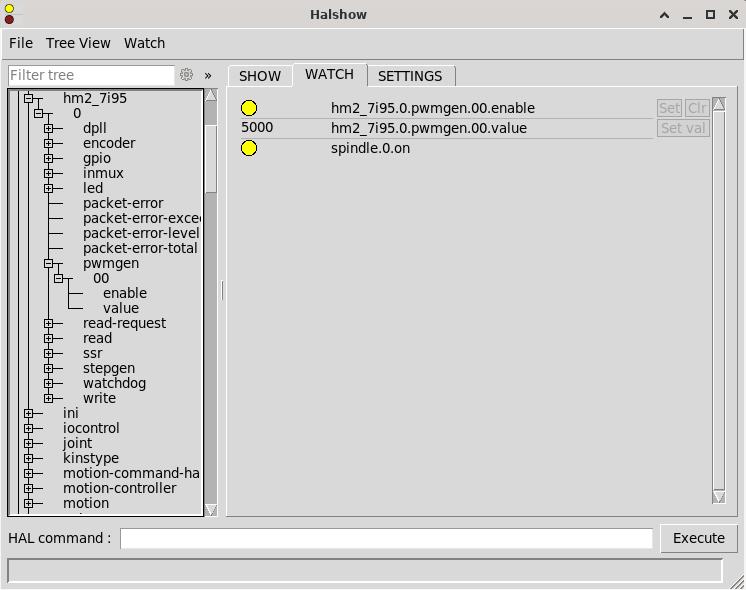
setp hm2_7i95.0.pwmgen.00.output-type 1
setp hm2_7i95.0.pwmgen.pwm_frequency 15000
setp hm2_7i95.0.pwmgen.00.scale 16000
net spindle-on <= spindle.0.on
net spindle-on => hm2_7i95.0.pwmgen.00.enable
net spindle-ramped => hm2_7i95.0.pwmgen.00.value
Attachments:
Please Log in or Create an account to join the conversation.
- PCW
-

- Away
- Moderator
-

Less
More
- Posts: 17929
- Thank you received: 5253
07 Feb 2025 16:01 #320920
by PCW
Replied by PCW on topic 7i95T + 7i78 spindle configuration
The (active low) analog enable on the 7I78 is
DB25 pin 6 (7I78 manual) = GPIO50 on that firmware.
So the hal file needs:
setp hm2_7i95.0.gpio.050.is_output
setp hm2_7i95.0.gpio.050.invert_output
net spindle-on => hm2_7i95.0.gpio.050.out
likewise, the direction pin is GPIO 51 so:
setp hm2_7i95.0.gpio.051.is_output
and GPIO 51 needs to be netted to the spindle direction signal
(and may need inversion depending on how it controls the VFD)
Its probably arguable that the firmware should have PWM enable
rather than GPIO control the 7I78s analog enable pin...
Please Log in or Create an account to join the conversation.
- tommy
- Offline
- Premium Member
-
Less
More
- Posts: 106
- Thank you received: 3
08 Feb 2025 11:01 - 08 Feb 2025 11:02 #320985
by tommy
Replied by tommy on topic 7i95T + 7i78 spindle configuration
Thank you for those lines, I'm now receiving signals!
Could you suggest the appropriate numbers for type, frequency, and scale?
I attempted the following settings, but I’m getting a +10V output at the spindle, even at M3 S9000. This should ideally be half of that value.
setp hm2_7i95.0.pwmgen.00.output-type 2
setp hm2_7i95.0.pwmgen.pwm_frequency 2000
setp hm2_7i95.0.pwmgen.00.scale 0
Last edit: 08 Feb 2025 11:02 by tommy.
Please Log in or Create an account to join the conversation.
- tommy
- Offline
- Premium Member
-
Less
More
- Posts: 106
- Thank you received: 3
08 Feb 2025 15:01 #320996
by tommy
Replied by tommy on topic 7i95T + 7i78 spindle configuration
Found the problem, as for my VFD pwmgen output has to be inverted (setp hm2_7i95.0.pwmgen.00.out0.invert_output true), after that scale started to work in right direction.
Please Log in or Create an account to join the conversation.
- tommy
- Offline
- Premium Member
-
Less
More
- Posts: 106
- Thank you received: 3
08 Feb 2025 17:00 #321006
by tommy
Replied by tommy on topic 7i95T + 7i78 spindle configuration
And there is one "last" thing, about enable signal. I'm using spindle soft start code in hal, as my vfd doesn't provide any feedback signals, and it works OK when starting (accel), but after M5, it immediately disables VFD, that means it doesn't wait for deceleration.
Is there a pin I could use for that?
My spindle soft start code
Is there a pin I could use for that?
My spindle soft start code
# load the real time modules limit2 and near with names so it is easier to follow their connections
loadrt limit2 names=spindle-ramp
loadrt near names=spindle-at-speed

# add the functions to a thread
addf spindle-ramp        servo-thread
addf spindle-at-speed    servo-thread

# set the parameter for max rate-of-change
# (max spindle accel/decel in units per second)
setp spindle-ramp.maxv 1200

# hijack the spindle speed out and send it to spindle ramp in
net spindle-cmd <= spindle.0.speed-out => spindle-ramp.in

# the output of spindle ramp is sent to the scale in
net spindle-ramped <= spindle-ramp.out => scale.0.in

# to know when to start the motion we send the near component
# (named spindle-at-speed) to the spindle commanded speed from
# the signal spindle-cmd and the actual spindle speed
# provided your spindle can accelerate at the maxv setting.
net spindle-cmd => spindle-at-speed.in1
net spindle-ramped => spindle-at-speed.in2

# the output from spindle-at-speed is sent to spindle.0.at-speed
# and when this is true motion will start
net spindle-ready <= spindle-at-speed.out => spindle.0.at-speed
Please Log in or Create an account to join the conversation.
- PCW
-
- Away
- Moderator
-
Less
More
- Posts: 17929
- Thank you received: 5253
08 Feb 2025 18:31 #321011
by PCW
Replied by PCW on topic 7i95T + 7i78 spindle configuration
If you are ramping the spindle speed you cannot use the PWM enable in the same way.
The PWM enable and 7I78 enable pin need to be driven by something like machine-on
in this case.
The PWM enable and 7I78 enable pin need to be driven by something like machine-on
in this case.
Please Log in or Create an account to join the conversation.
- tommy
- Offline
- Premium Member
-
Less
More
- Posts: 106
- Thank you received: 3
10 Feb 2025 09:05 #321146
by tommy
Replied by tommy on topic 7i95T + 7i78 spindle configuration
I ment hm2_7i95.0.gpio.050.outoutput which enable/disable vfd.
I solved it with additional near component, which outputs true when in my case spindle-ramped is at zero, and this output is inverted, so I can use it for VFD enable.
Code below, if someone in future faces similar problem:
I solved it with additional near component, which outputs true when in my case spindle-ramped is at zero, and this output is inverted, so I can use it for VFD enable.
Code below, if someone in future faces similar problem:
# -------SPINDLE SOFT START --------------------------------------

# load the real time modules limit2 and near with names so it is easier to follow their connections
loadrt limit2 names=spindle-ramp
loadrt near names=spindle-at-speed,spindle-zero

# add the functions to a thread
addf spindle-ramp        servo-thread
addf spindle-at-speed    servo-thread

# spimdle-zero pin used for enabeling vfd and disabeling after decel is finished
addf spindle-zero        servo-thread

# set the parameter for max rate-of-change
# (max spindle accel/decel in units per second)
setp spindle-ramp.maxv 1100

# hijack the spindle speed out and send it to spindle ramp in
net spindle-cmd <= spindle.0.speed-out => spindle-ramp.in

# the output of spindle ramp is sent to the scale in
net spindle-ramped <= spindle-ramp.out => scale.0.in

# to know when to start the motion we send the near component
# (named spindle-at-speed) to the spindle commanded speed from
# the signal spindle-cmd and the actual spindle speed
# provided your spindle can accelerate at the maxv setting.
net spindle-cmd => spindle-at-speed.in1
net spindle-ramped => spindle-at-speed.in2

# setting first input of second near input to 0
setp spindle-zero.in1 0

# sending actual spindle speed to second input of second near module
net spindle-ramped => spindle-zero.in2

# the output from spindle-at-speed is sent to spindle.0.at-speed
# and when this is true motion will start
net spindle-ready <= spindle-at-speed.out => spindle.0.at-speed

# ---------- SPIDNLE OUT -----------

setp hm2_7i95.0.gpio.050.is_output 1

# spindle-zero.out is used for delaying VFD disable to wait spindle ramp down till stops spining
net sindle-enbl spindle-zero.out => hm2_7i95.0.gpio.050.out

setp hm2_7i95.0.pwmgen.00.out0.invert_output true
setp hm2_7i95.0.pwmgen.pwm_frequency 2000
setp hm2_7i95.0.pwmgen.00.scale 16500
net spindle-on <= spindle.0.on
net spindle-on => hm2_7i95.0.pwmgen.00.enable
net spindle-ramped => hm2_7i95.0.pwmgen.00.value
Please Log in or Create an account to join the conversation.
Time to create page: 0.139 seconds