Setting up kinematics for my Ballscrew articulated B-axis
- Gautham
- Offline
- Junior Member
-

Less
More
- Posts: 32
- Thank you received: 3
22 Sep 2025 05:53 #335266
by Gautham
Setting up kinematics for my Ballscrew articulated B-axis was created by Gautham
Hi everyone,
So I have my B-axis articulated by a ballscrew, as you might have guessed, and I am having some trouble understanding kinematics and how to set this up in LinuxCNC. Below is a picture of my design, followed by a drawing of the geometry. My trouble isn't with getting the math correct, so you can ignore the math if you wish. I need help understanding how to input this into LinuxCNC. So far I have followed this tutorial, but I have got stuck with the kinematics part.
 And the geometry

So to describe the drawing
DEH
So if I were to write a function to find the angle of the spindle(FEH) relative to the Z-axis based on the length of AC, it would be as follows
So first, we will calculate the length CE based on the length CH
CE = sqrt(CH2 +HE2) where HE = 120
CE = sqrt(CH2 +1202)
CE = sqrt(CH2 + 14400)
Now we can calculate angle DEC and subtract angle DEF to get the angle of the spindle
COS(DEC) = (1272 + CE2 - 1252)/(2*127*CE)
COS(DEC) = (1272 + CH2 + 14400 - 1252)/(2*127*sqrt(CH2 + 14400))
COS(DEC) = (CH2 - 14904) / (254*sqrt(CH2 + 14400))
where CH = AC - AH = AC-217
If you are not interested in the math, please continue reading here
So if COS(DEC) = (CH2 - 14904) / (254*sqrt(CH2 + 14400)) - DEF describes the relation of the ballscrew moving to the rotation of the B-axis how do I set this up in LinuxCNC? Also, do I need to calculate the formula for the tool tip change in X-axis and Z axis based on the B-axis rotating as well, before inputting this into LinuxCNC or is this sufficient? Thank you for your help and patience
So I have my B-axis articulated by a ballscrew, as you might have guessed, and I am having some trouble understanding kinematics and how to set this up in LinuxCNC. Below is a picture of my design, followed by a drawing of the geometry. My trouble isn't with getting the math correct, so you can ignore the math if you wish. I need help understanding how to input this into LinuxCNC. So far I have followed this tutorial, but I have got stuck with the kinematics part.
So to describe the drawing
- Line CD is a connecting rod where point C travels along the ballscrew path AB, and the path is perpendicular to the Z-axis
- Point H is a point along the path AB that is directly above point E, that is, angle BHE will always be 90 deg and the distance HE is 120mm and AH is 217mm
- Point E is the centre of the B-axis rotation
- Point D represents where the connecting rod is connected to the B-axis assembly
- Line FG is the spindle where G is the tool tip.
- CD = 125mm
- DE = 127mm
- EG = 120mm
- HE = 120
- Angle DEF = 30.579 deg
DEH
So if I were to write a function to find the angle of the spindle(FEH) relative to the Z-axis based on the length of AC, it would be as follows
So first, we will calculate the length CE based on the length CH
CE = sqrt(CH2 +HE2) where HE = 120
CE = sqrt(CH2 +1202)
CE = sqrt(CH2 + 14400)
Now we can calculate angle DEC and subtract angle DEF to get the angle of the spindle
COS(DEC) = (1272 + CE2 - 1252)/(2*127*CE)
COS(DEC) = (1272 + CH2 + 14400 - 1252)/(2*127*sqrt(CH2 + 14400))
COS(DEC) = (CH2 - 14904) / (254*sqrt(CH2 + 14400))
where CH = AC - AH = AC-217
If you are not interested in the math, please continue reading here
So if COS(DEC) = (CH2 - 14904) / (254*sqrt(CH2 + 14400)) - DEF describes the relation of the ballscrew moving to the rotation of the B-axis how do I set this up in LinuxCNC? Also, do I need to calculate the formula for the tool tip change in X-axis and Z axis based on the B-axis rotating as well, before inputting this into LinuxCNC or is this sufficient? Thank you for your help and patience
Please Log in or Create an account to join the conversation.
- tommylight
-

- Offline
- Moderator
-

Less
More
- Posts: 21764
- Thank you received: 7438
22 Sep 2025 16:23 #335288
by tommylight
And do not advise anyone to upload pictures to third party sites, they are not safe, just google "malware on file sharing websites" and be amazed.
GitHUB is OK, though, for now.
Replied by tommylight on topic Setting up kinematics for my Ballscrew articulated B-axis
Works fine here.Your image links don't work.
And do not advise anyone to upload pictures to third party sites, they are not safe, just google "malware on file sharing websites" and be amazed.
GitHUB is OK, though, for now.
Please Log in or Create an account to join the conversation.
- Hakan
- Offline
- Platinum Member
-

Less
More
- Posts: 1317
- Thank you received: 453
22 Sep 2025 16:49 #335291
by Hakan
Replied by Hakan on topic Setting up kinematics for my Ballscrew articulated B-axis
Picture is fine.
linuxcnc.org/docs/html/motion/kinematics.html is a starting point if you haven't been there already.
linuxcnc.org/docs/html/motion/kinematics.html is a starting point if you haven't been there already.
The following user(s) said Thank You: tommylight
Please Log in or Create an account to join the conversation.
- Gautham
- Offline
- Junior Member
-
Less
More
- Posts: 32
- Thank you received: 3
23 Sep 2025 04:53 - 23 Sep 2025 09:21 #335316
by Gautham
Replied by Gautham on topic Setting up kinematics for my Ballscrew articulated B-axis
Ok, sorry for the images. Anyway, I performed all the math on Google Sheets, so you can enter the B-axis position on the ball screw, and it will provide you with the spindle angle, the tooltip x-offset, and the tooltip z-offset. The range of travel for the B-axis is 0 to 305mm. You can enter this in cell Y11, and it will spit out the results. I have also illustrated the drawings better here so that hopefully you can understand.
Here is the link
. I have looked at the Kinematics tutorial on the website, but I just learn better if I can see someone do a working example. After hours of reading that with Gemini helping with some of the explanations, I don't know how to start writing the code. Anyway, from the tutorial I posted earlier, there is an image of this person's kinematicsInverse function, which I will insert below.
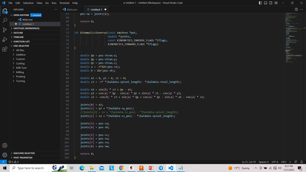
From what I've understood, the job of this function is to understand the required tool tip movement and spit out the number of steps each axis motor needs to make, correct? If that is correct, I should be able to modify the trigonometry here to accommodate my ballscrew articulated B-axis and get this going, hopefully. Because his setup also has an XYZAB setup similar to mine.
From what I've understood, the job of this function is to understand the required tool tip movement and spit out the number of steps each axis motor needs to make, correct? If that is correct, I should be able to modify the trigonometry here to accommodate my ballscrew articulated B-axis and get this going, hopefully. Because his setup also has an XYZAB setup similar to mine.
Last edit: 23 Sep 2025 09:21 by Gautham. Reason: It was wierd earlier
Please Log in or Create an account to join the conversation.
- Aciera
-

- Offline
- Administrator
-

Less
More
- Posts: 4766
- Thank you received: 2138
23 Sep 2025 13:22 - 23 Sep 2025 13:31 #335322
by Aciera
Replied by Aciera on topic Setting up kinematics for my Ballscrew articulated B-axis
Personally I would suggest tp use the .comp format:
linuxcnc.org/docs/2.9/html/man/man9/userkins.9.html
But regardless,
Forward kinematic uses the joint positions to calculate the cartesian coordinate positions
Inverse kinematic uses the cartesian coordinate positions (ie the position commands of the motion planner) to calculate the joint positions (ie basically the commands that get sent to your motor drives)
One needs to be the mathematical inverse of the other (otherwise the values will run off and you will get limit violation errors)
Last edit: 23 Sep 2025 13:31 by Aciera.
Please Log in or Create an account to join the conversation.
- Gautham
- Offline
- Junior Member
-
Less
More
- Posts: 32
- Thank you received: 3
08 Oct 2025 01:45 #336074
by Gautham
Replied by Gautham on topic Setting up kinematics for my Ballscrew articulated B-axis
Hi sorry for the late reply, I was on holiday. Thank you, Aciera. I am new to this, so I will go through the link you sent and try to understand it. Is there any reason you would go the route of using the .comp format? Thanks for the input
Please Log in or Create an account to join the conversation.
Time to create page: 0.108 seconds