Repair Servodrive Yaskawa CACR
- aleksamc
-
 Topic Author
- Offline
- Platinum Member
-

Less
More
- Posts: 569
- Thank you received: 67
22 Mar 2021 13:41 - 22 Mar 2021 13:56 #203244
by aleksamc
Repair Servodrive Yaskawa CACR was created by aleksamc
I write this topic in hope that here is somebody who knows this servodrives and electronics.
I separete this topic from another branch where I made refit of CNC Biesse Rover 346.
When I almost finished refit and everything worked fine, one servodrive YASKAWA CACR-SR10BE12G-E fell down. It’s led are light down.
I took it home in hope to repair it.
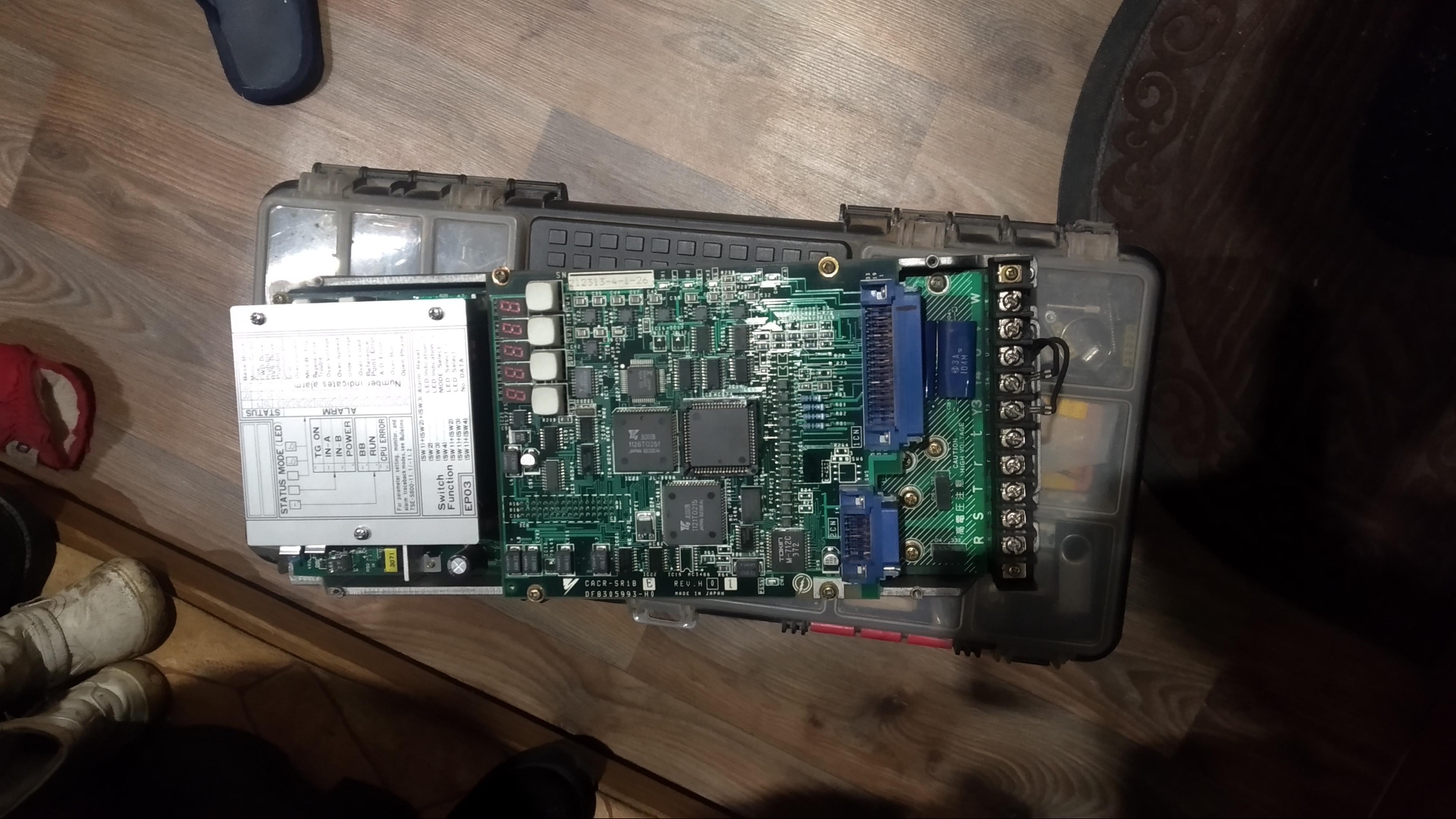
Picture 1
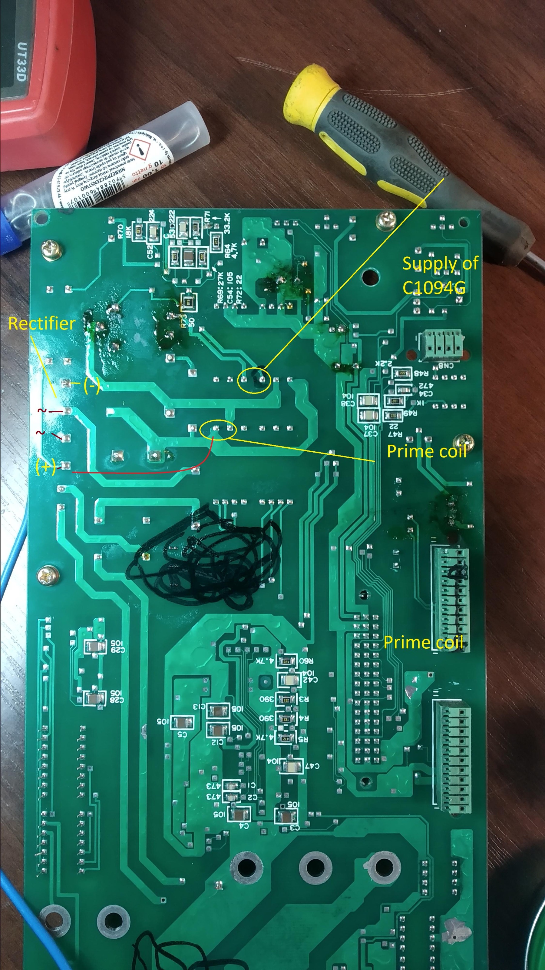
When I opened it, I found that problem in the part of it’s Power Supply.
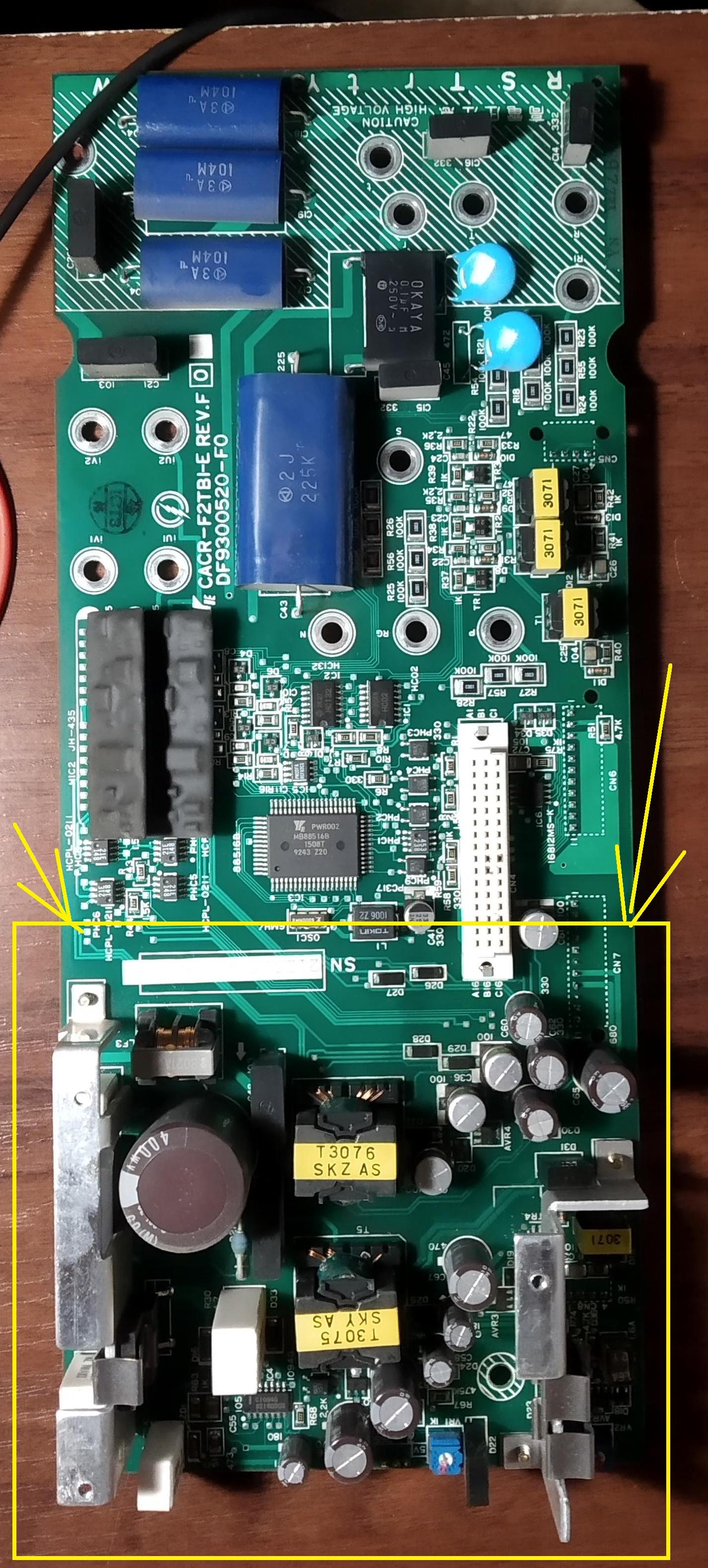
Picture 2
I found that problem made stabilitron, that was short circuited. I changed it to another 36V (I don’t know I’m right). Also resistor 4,7kOhm and 5W power was also shortcurcuited and I changed it. In the same way I changed Mosfet FEC 2SK1212 that was in that curcuit.
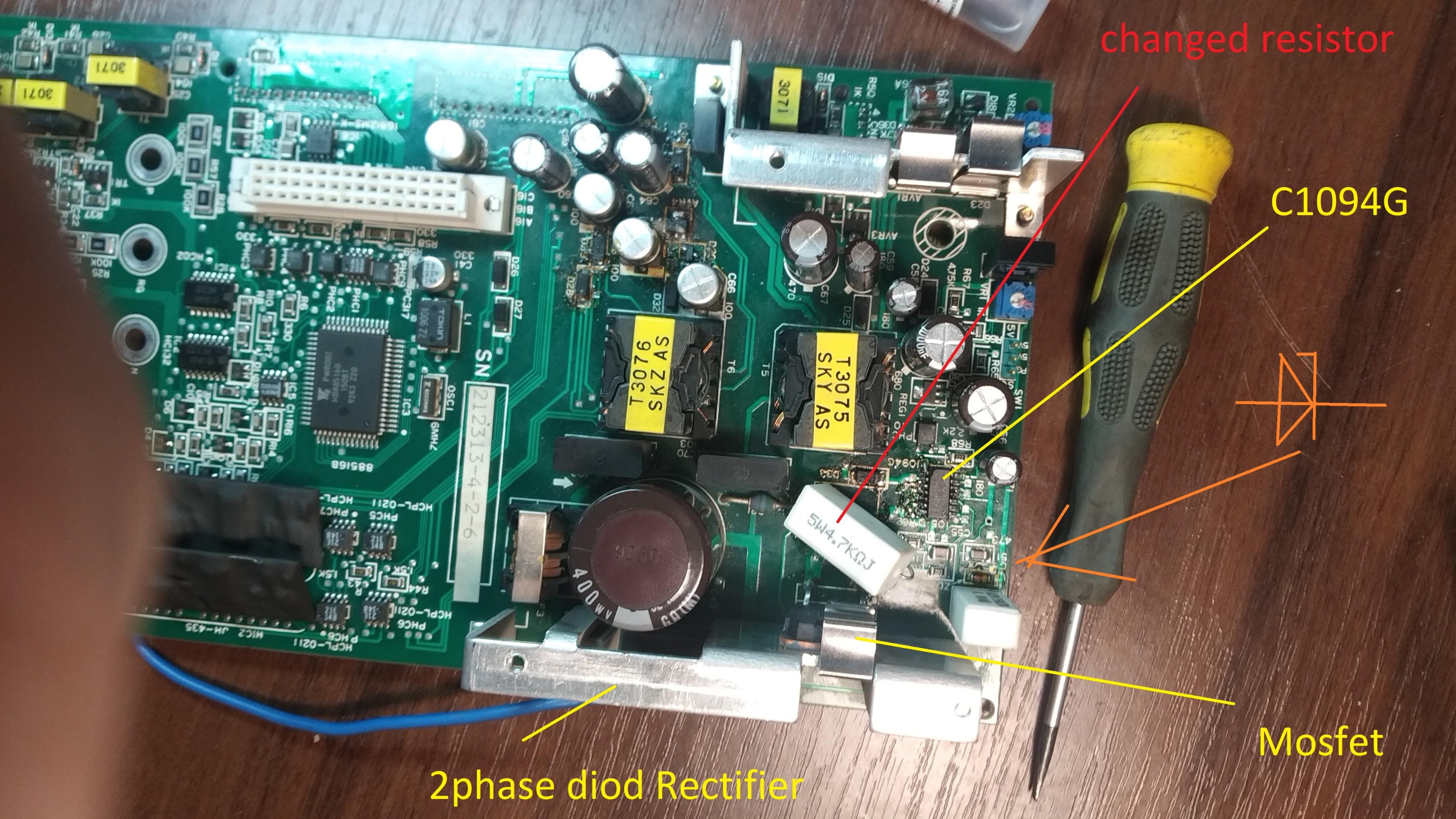
Picture 3
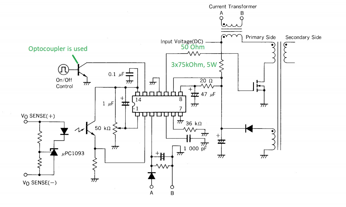
Also I changed C1094G that control power supply of that board. I add main schematic of it also.
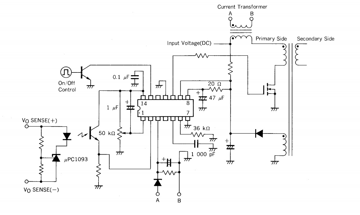
Pict 4
But servodrive still doesn’t work. I found that there is no voltage on this C1094G. And It takes it from transformer that on primary coil has DC 300V from rectifier.
It's very big question for me: how this board can get supply from secondary coil of the transoformer that it should control.
Does anybody have some thoghts about my problem?
And one more moment: If I change this board with one from another servodrive, everything works. So problem only on this board.
I separete this topic from another branch where I made refit of CNC Biesse Rover 346.
When I almost finished refit and everything worked fine, one servodrive YASKAWA CACR-SR10BE12G-E fell down. It’s led are light down.
I took it home in hope to repair it.
Picture 1
When I opened it, I found that problem in the part of it’s Power Supply.
Picture 2
I found that problem made stabilitron, that was short circuited. I changed it to another 36V (I don’t know I’m right). Also resistor 4,7kOhm and 5W power was also shortcurcuited and I changed it. In the same way I changed Mosfet FEC 2SK1212 that was in that curcuit.
Picture 3
Also I changed C1094G that control power supply of that board. I add main schematic of it also.
Pict 4
But servodrive still doesn’t work. I found that there is no voltage on this C1094G. And It takes it from transformer that on primary coil has DC 300V from rectifier.
It's very big question for me: how this board can get supply from secondary coil of the transoformer that it should control.
Does anybody have some thoghts about my problem?
And one more moment: If I change this board with one from another servodrive, everything works. So problem only on this board.
Last edit: 22 Mar 2021 13:56 by aleksamc.
Please Log in or Create an account to join the conversation.
- arvidb
-

- Offline
- Platinum Member
-
Less
More
- Posts: 459
- Thank you received: 158
22 Mar 2021 14:50 #203246
by arvidb
Replied by arvidb on topic Repair Servodrive Yaskawa CACR
That C1094G schematic looks strange indeed. Absolute max voltage Vcc-GND is listed as 26 VDC in the data sheet, but in that circuit there is nothing that I can see that prevents almost the full input voltage of >300 VDC from appearing on Vcc, when the circuit is idle. If that 4.7 kΩ resistor is in series with Vcc the IC needs to draw >60 mA continously for the voltage rating to be kept.
It's pretty badly drawn, too, compared to the data sheets of modern primary-switched controllers. I'm guessing Yaskawa has modified the circuit somewhat. Maybe that zener diode is regulating Vcc for C1094G? Or is that the feedback shunt regulator (µPC1093)?
It's pretty badly drawn, too, compared to the data sheets of modern primary-switched controllers. I'm guessing Yaskawa has modified the circuit somewhat. Maybe that zener diode is regulating Vcc for C1094G? Or is that the feedback shunt regulator (µPC1093)?
Please Log in or Create an account to join the conversation.
- tommylight
-

- Away
- Moderator
-

Less
More
- Posts: 21690
- Thank you received: 7412
22 Mar 2021 15:55 #203257
by tommylight
Replied by tommylight on topic Repair Servodrive Yaskawa CACR
From the schematics the C1094G looks like it is TL494 so there is plenty of stuff using it:
www.google.com/search?q=tl494&source=hp&...KLDpgQ4dUDCAY&uact=5
www.google.com/search?q=tl494&source=hp&...KLDpgQ4dUDCAY&uact=5
Please Log in or Create an account to join the conversation.
- arvidb
-
- Offline
- Platinum Member
-
Less
More
- Posts: 459
- Thank you received: 158
22 Mar 2021 16:22 #203260
by arvidb
Replied by arvidb on topic Repair Servodrive Yaskawa CACR
They are not the same: different pinout (even different number of pins). Although TL494 lists isolated AC/DC power supplies in its list of applications, there are no schematics in its data sheet on how to use it for that application - all example schematics show low-voltage non-isolated switching.
Please Log in or Create an account to join the conversation.
- Aciera
-

- Offline
- Administrator
-

Less
More
- Posts: 4734
- Thank you received: 2121
22 Mar 2021 16:40 - 22 Mar 2021 16:42 #203261
by Aciera
Replied by Aciera on topic Repair Servodrive Yaskawa CACR
Have you checked the "On/Off Control" signal? Does the logic processor get powered up at all?
Last edit: 22 Mar 2021 16:42 by Aciera.
Please Log in or Create an account to join the conversation.
- Muzzer
- Offline
- Elite Member
-

Less
More
- Posts: 266
- Thank you received: 42
22 Mar 2021 18:04 - 22 Mar 2021 18:10 #203273
by Muzzer
Replied by Muzzer on topic Repair Servodrive Yaskawa CACR
I've been a power electronics engineer for several decades and although I've not used this particular device, its function is pretty clear to me. I wouldn't be surprised if the part number is a Yaskawa special.
The IC is started up by a small current trickled down from "input voltage (DC)" into pin 8. This is likely to be around 1mA or so. Once the 47uF capacitor (and its un-named friend) have reached the startup threshold, the FET starts to switch and the little winding on the bottom right of the diagram should then provide the ongoing power for the control circuit. Until that has been established, the output to the FET will be a series of pulses ("burst mode") as the 47uF cap discharges from the startup threshold down to the undervoltage threshold.
It's not obvious why it would have popped but the electrolytic caps dry out with temperature and time, at which point they cease to behave like the capacitors that were designed in. You may be advised to change them for new ones. Also check the resistor between the FET and the IC. When FETs pop, they tend to send a big voltage back out of the gate pin. As well as damaging the controller IC, this can also blow the resistor.
Judging by the date code on the big IC (9243 ie 1992 week 43), this board was made in late 1992 or early 1993. That's almost 30 years ago, so it wouldn't be surprising if many of the caps have dried out. The large electrolytics on the inverter stage are considered serviceable items and the same might almost be said for the forest of smaller ones.
For the fully retentive, the phase dots on the transformer windings are wrong, as this is a flyback power supply. Sorry, I couldn't let that one go.
Last edit: 22 Mar 2021 18:10 by Muzzer.
The following user(s) said Thank You: arvidb, tommylight, aleksamc
Please Log in or Create an account to join the conversation.
- aleksamc
-
Topic Author
- Offline
- Platinum Member
-
Less
More
- Posts: 569
- Thank you received: 67
23 Mar 2021 08:18 - 23 Mar 2021 08:21 #203359
by aleksamc
Replied by aleksamc on topic Repair Servodrive Yaskawa CACR
Thank you very much all about interest to my problem. Really I didn't wait so much answers to see. Thank you Muzzer that you clearified for me basics for this IC. Now I'm much closer to solving this problem.
I have checked, what resistance I have on unknown "friends", it's 3 resistors of 75kOhm Values.
Also, As Acierra wrtote, I add schematic of control pins.
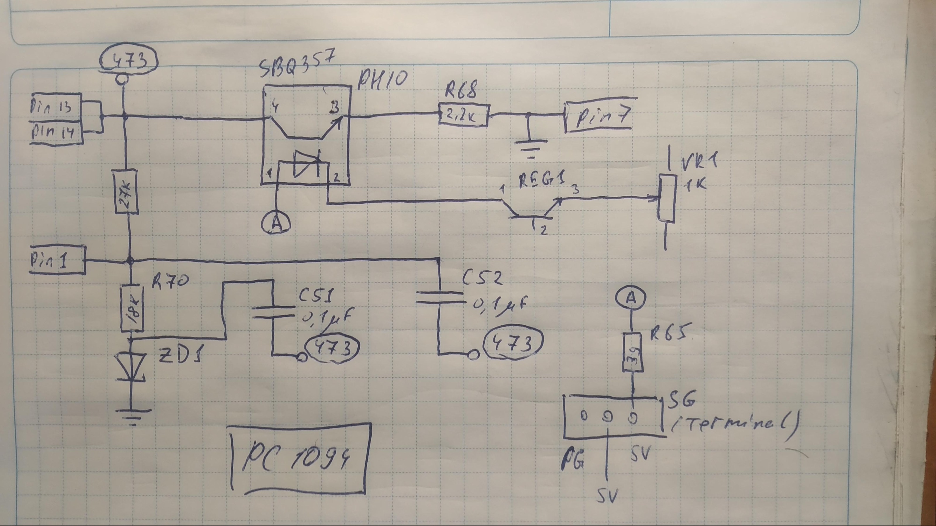
There is stabilitron ZD1. It was shorted and I changed it to 36V.
Really, I don't understand:
- what part it takes in control;
- what voltage it should have to regulate reference voltage (reference voltage of the 1094G is 5V from datasheet)
- and why it turned to GND?
Can somebody clearify for me thees?
And yes, there is on terminal SG I have all 0V, so optocoupler PH10 can't be opened.
I have checked, what resistance I have on unknown "friends", it's 3 resistors of 75kOhm Values.
Also, As Acierra wrtote, I add schematic of control pins.
There is stabilitron ZD1. It was shorted and I changed it to 36V.
Really, I don't understand:
- what part it takes in control;
- what voltage it should have to regulate reference voltage (reference voltage of the 1094G is 5V from datasheet)
- and why it turned to GND?
Can somebody clearify for me thees?
And yes, there is on terminal SG I have all 0V, so optocoupler PH10 can't be opened.
Attachments:
Last edit: 23 Mar 2021 08:21 by aleksamc.
Please Log in or Create an account to join the conversation.
- Aciera
-
- Offline
- Administrator
-
Less
More
- Posts: 4734
- Thank you received: 2121
23 Mar 2021 10:05 #203370
by Aciera
Have you actually measured the resistance of pin13 to GND?
Can you measure any voltage between VCC and GND?
Have you checked the resistance of the transformer windings ?
Do you have an oszilloscope to check if there is any activity on Pin10 at all?
Replied by Aciera on topic Repair Servodrive Yaskawa CACR
And yes, there is on terminal SG I have all 0V, so optocoupler PH10 can't be opened.
Have you actually measured the resistance of pin13 to GND?
Can you measure any voltage between VCC and GND?
Have you checked the resistance of the transformer windings ?
Do you have an oszilloscope to check if there is any activity on Pin10 at all?
The following user(s) said Thank You: aleksamc
Please Log in or Create an account to join the conversation.
- bevins
-
- Offline
- Platinum Member
-
Less
More
- Posts: 1942
- Thank you received: 338
23 Mar 2021 22:08 #203446
by bevins
Replied by bevins on topic Repair Servodrive Yaskawa CACR
There is a hidden breaker on the bottom back. That trips sometimes. Has happen to me on my Biesse 346 more than once.
Please Log in or Create an account to join the conversation.
- sivaraj
- Offline
- Senior Member
-

Less
More
- Posts: 50
- Thank you received: 25
24 Mar 2021 03:40 - 24 Mar 2021 04:55 #203481
by sivaraj
Replied by sivaraj on topic Repair Servodrive Yaskawa CACR
Logically those ceramic resistor cannot get short circuited .Either it will become open circuit or change in actual values over time - most likely may increase .
I do not understand which diode you replaced with 36V zener.
Which diode in the schematic ?
Verify this diode with the good working PCB by checking the voltage across particular diode.If it is really a zener diode it will show the voltage .
As per reference schematic it involves two IC's to control power supply.
upc1094 & upc1093 .
The UPC1094 is control for power supply output.
upc1093 controls the feedback & internal reference voltage to the circuit .
if the zener diode which you replaced is in the place of upc1093 it cannot be 36v.
As per the spec sheet the upc1093 is for 2.495V or 2.5V reference voltage.
Also it appears the section you are repairing is for 5v.There is no need for 36v
However UPC1094 requires 15V typical to operate.
If you apply power to the drive there should be around 15v on IC pin 8 which is derived from main dc voltage .
Further if UPC1094 is in good condition there will be a reference voltage on IC pin 14.
The Ct on pin 5 and Rt pin 6 are critical .
Check it is values
I suspect Ct could be the initial cause to fail . Even if Ct looks good try replace to a new one with exact same value .
If everything is normal there should be ramp pulse on pin 5 .
The IC Pin 13 works like an enable circuit.
In hand drawn schematic the ZD1 direction is not right. if it is really a zener it should be opposite- Anode is grounded
Last edit: 24 Mar 2021 04:55 by sivaraj. Reason: additional info
The following user(s) said Thank You: aleksamc
Please Log in or Create an account to join the conversation.
Time to create page: 0.359 seconds