Repair Servodrive Yaskawa CACR
- aleksamc
-
 Topic Author
- Offline
- Platinum Member
-

- Posts: 569
- Thank you received: 67
I have 16,7kOhm on broken and 17,8kOhm on workable. It's very grate that I can compareHave you actually measured the resistance of pin13 to GND?
Voltage on Vcc and GND is 3.2V, because I replaced 36V zener diod to 3.3V (that I have). I will write about it later...Can you measure any voltage between VCC and GND?
Transformer windings resistance is on normal and corresponds to working one.Have you checked the resistance of the transformer windings ?
Do you have an oszilloscope to check if there is any activity on Pin10 at all?So I connected workable drive and check VCC - GND voltage and Zener Diod Voltage ZD1. They are equal to 12.5V.
So, conclusions that I made besicaly on your directional questions:
- ZD1 (zener diod) is used to regulate voltage VCC-GND of IC and is equal to 12.5V.
So, I will buy capasitors, zener diod and change. Hope it will work.
After I will do all this I will write about results. But Currently I thank to all you my friend, that help be to woek in right way!
Please Log in or Create an account to join the conversation.
- sivaraj
- Offline
- Senior Member
-

- Posts: 50
- Thank you received: 25
As per datasheet upc1094's maximum absolute rating is 26V.
So anything using above 26V will not protect the upc1094 .
There is no meaning in using a 36v zener diode on VCC .
Votage across VCC-Gnd may fluctuate based on incoming supply voltage and the zener protects maximum voltage applied
Please Log in or Create an account to join the conversation.
- aleksamc
-
Topic Author
- Offline
- Platinum Member
-
- Posts: 569
- Thank you received: 67
On working servodrive ZD1 =12.5V. I have ordered already such voltage to try, hope it will work.
As for my schematic, where anode of ZD1 is connected to gnd, I was wrong in that, cathode s connected to gnd, but not zd1 rotated on schematic, simply gnd in other place.
Initialy, ZD1 was shorted and I replaced it with that I had. It was 36V.
Please Log in or Create an account to join the conversation.
- Muzzer
- Offline
- Elite Member
-

- Posts: 266
- Thank you received: 42
The output on pin 10 should be a series of trains of pulses. This sounds as if it may be happening. Then, when the transformer is being switched, the supply voltage at pins 8 & 9 should rise and stabilise to something around 12V or so. Is there an output on the secondary winding ("secondary side")? Check the output rectifier diode isn't short circuit, otherwise it will see an overcurrent and never start up. During those pulses, the output voltage should ramp up. Is there a short on the secondary circuit after the diode?
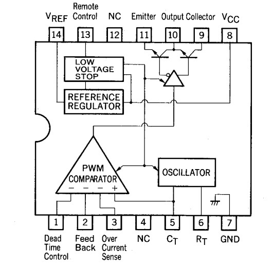
Pin 14 is presumably a reference voltage, most likely 5V. Pin 1 will be the set voltage for an internal opamp and pin 2 the feedback voltage - these 2 pins should end up at the same voltage when it regulating. Pin 3 is a current signal input from the current transformer (don't disconnect that - it may be saving you from a bigger problem!). Pins 5 & 6 look like the timing R & C, which seem unlikely to have been damaged.
The uPC1093 is almost certainly a LM431 / TL431 device. It basically turns on the opto when the secondary voltage reaches the set point and thus regulates the output.
It looks fairly conventional on the face of it but I can't understand what this zener is about. You need to trace the tracking more carefully so that we can make sense of it but the sketch can't be right as you've shown it.
Please Log in or Create an account to join the conversation.
- aleksamc
-
Topic Author
- Offline
- Platinum Member
-
- Posts: 569
- Thank you received: 67
There are on board test points, that has number sign. So 473 is point on board where you can check voltage. You see few points with the same number because this is one node, it's for easiness of reading.I don't understand the hand drawn circuit. What does "473" mean?
I received and resoldered capacitors and zener dioid for 12V. But it still not work.
I attach osciloscope graphs for C1094-Pin10 (green color) and Mosfet-Pin3 (yellow color).
In short period I see such series of pulses:
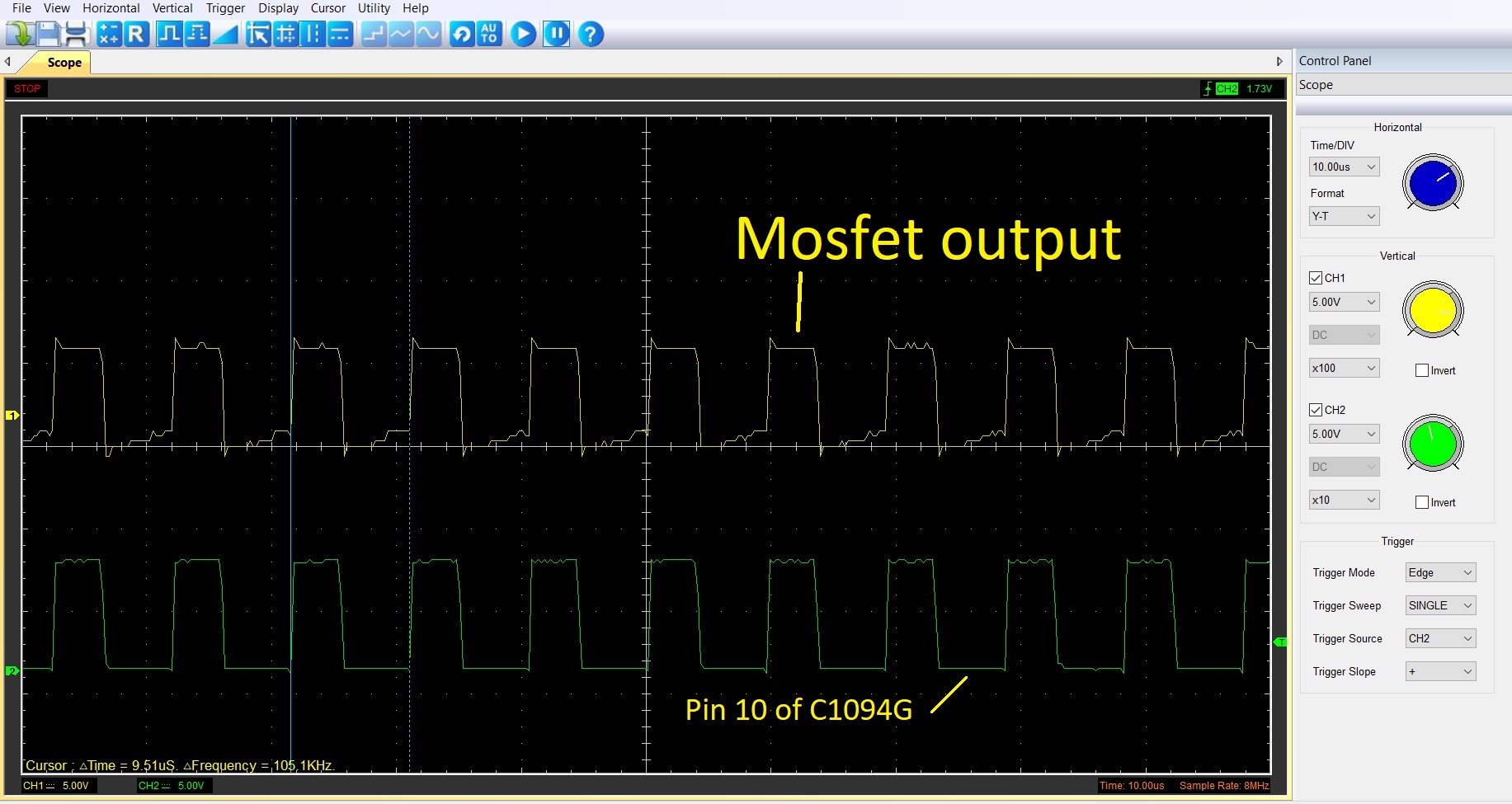
But it goes periodicaly, in large scale you can see:
So, voltage between pins 7 -8 (gnd - VCC) is 9,3V. This voltage is equal to voltage on zener diod ZD1.
On pin 13 I have allways High voltage (9.3V), nevertheless if series of pulses are present.
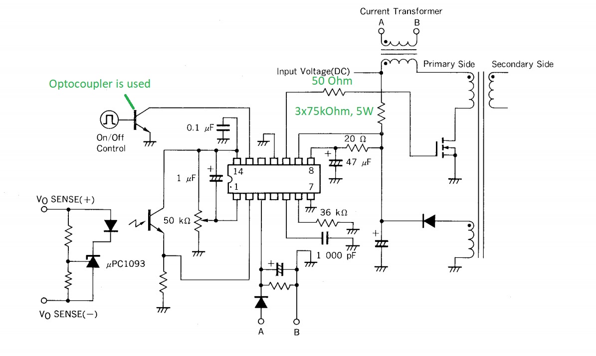
PC1093 is not installed on this board. It's installed ZD1 instead.
Does anybody has some thought or questions what to measure?
Attachments:
Please Log in or Create an account to join the conversation.
- aleksamc
-
Topic Author
- Offline
- Platinum Member
-
- Posts: 569
- Thank you received: 67
Then, when the transformer is being switched, the supply voltage at pins 8 & 9 should rise and stabilise to something around 12V or so.
I measure voltage between pins 8 & 9, voltage is equal 0.
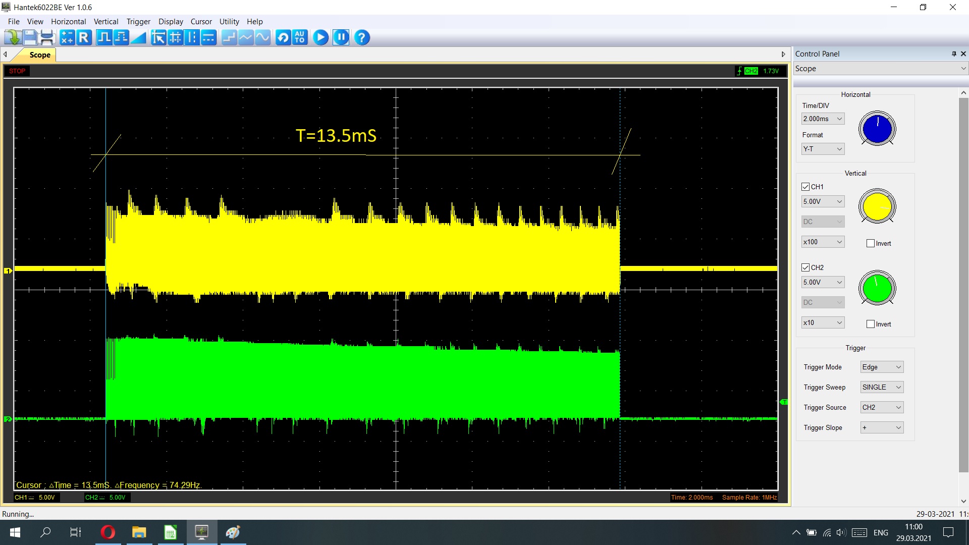
Also I measured voltage between GND and Pin 9, it has such behavior:
1) When series of pulses run, voltage on pin .9 also increase, but fast.
2) when voltage on pin 9 gets to some value, Pulses stops
3) Voltage on Pin 9 slowly decreasing
4) When voltage on Pin 9 decrease to some value (8-9 Volts I think), Mosfet starts to generate pulses
1) all repeats.
Please Log in or Create an account to join the conversation.
- Aciera
-

- Offline
- Administrator
-

- Posts: 4754
- Thank you received: 2134
So, voltage between pins 7 -8 (gnd - VCC) is 9,3V
According to the datasheet the C1094 requires a minimum supply voltage of 11V so this might not be enough to get the chip into regular operation.
The IC is started up by a small current trickled down from "input voltage (DC)" into pin 8. This is likely to be around 1mA or so. Once the 47uF capacitor (and its un-named friend) have reached the startup threshold, the FET starts to switch and the little winding on the bottom right of the diagram should then provide the ongoing power for the control circuit. Until that has been established, the output to the FET will be a series of pulses ("burst mode") as the 47uF cap discharges from the startup threshold down to the undervoltage threshold.
Your screenshot seems to show the startup burst mode but VCC doesn't seem to reach it's proper level.
[edit]
I received and resoldered capacitors and zener dioid for 12V
Are you sure the voltage rating of the zener is supposed to be 12V? Have you checked that with one of the working drives?
Please Log in or Create an account to join the conversation.
- aleksamc
-
Topic Author
- Offline
- Platinum Member
-
- Posts: 569
- Thank you received: 67
There is on secondary coil no shortcuircuit and diod is good.Check the output rectifier diode isn't short circuit, otherwise it will see an overcurrent and never start up. During those pulses, the output voltage should ramp up. Is there a short on the secondary circuit after the diode?
I check on working one and on zener diod there was 12V or so and it worked fine.Are you sure the voltage rating of the zener is supposed to be 12V? Have you checked that with one of the working drives?
From osciloscope I see that I have 105kHz pulse period in datasheet pulse period 50.. 500kHz.
Need I increase oscilating freaquency to get stable work?
Please Log in or Create an account to join the conversation.
- aleksamc
-
Topic Author
- Offline
- Platinum Member
-
- Posts: 569
- Thank you received: 67
I changed ZD1 diod from 12V to 25V but voltage gnd-vcc doesn't change, still 9.3V
Also I measured pins voltage on IC:Pins 5 - 6 = 4,3V
Pins 1 - 5 =3.9 ~ 4,1 (vary)
Pins 2 - 5=0V
Pins 3 - 5=0V
Pins 7 - 14=5V
Pins 7 - 13=5V
And output control terminal where should be GND - 5V - 5V, I get Gnd - 0V - 0.18V
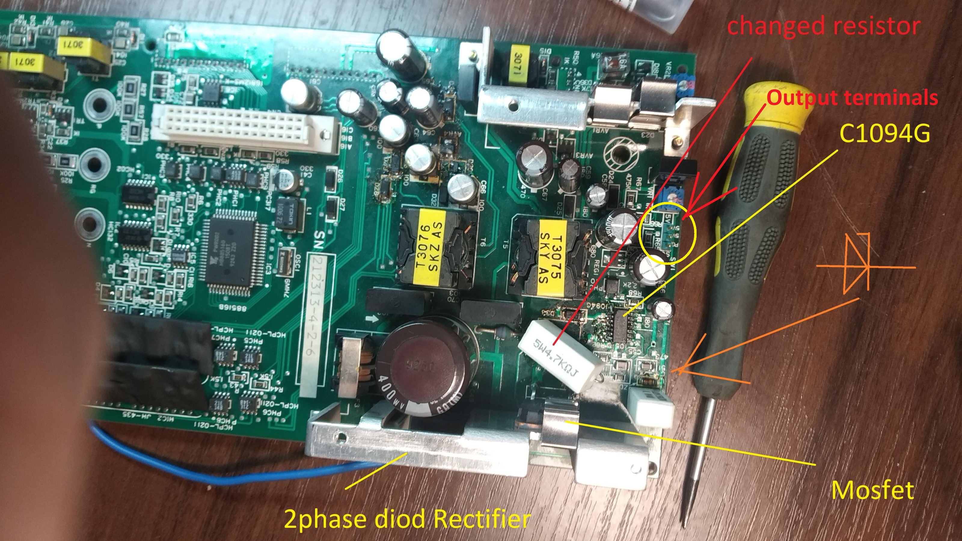
Attachments:
Please Log in or Create an account to join the conversation.
- sivaraj
- Offline
- Senior Member
-
- Posts: 50
- Thank you received: 25
1. Input voltage(DC) > Most likely it is about 240vdc if it is derived from source of 200Vac
2. Votage at PIN-9 of IC
3. Votage at PIN-8 of IC which should be min-11V max-26V
Anything under 11v at pin-8 is not a normal condition .IC will not work.
In the reference schematic a resistor marked as 3x75Kohm,5w .Are they connected in series or parallel
You have changed a 4.7K 5W resistor . Which resistor is this .
This ceramic resitor cannot become a short circuit .
Recheck the value with the good working card .
Or By any chance did you replace the the marked 3x75Kohm,5w with 4.7k 5w resistor ?
At Pin-5 you must use scope to check. It will have ramp pulse - This circuit has interlock may not work if there is under voltage.
sometime the Ct capacitor will fail due to aging degrade
Please Log in or Create an account to join the conversation.