Do you really need a spring loaded pinion drive?
- rodw
-
 Topic Author
- Offline
- Platinum Member
-

Less
More
- Posts: 11854
- Thank you received: 4019
01 Sep 2016 10:50 #79823
by rodw
Do you really need a spring loaded pinion drive? was created by rodw
From what I've read when you use a rack and pinion drive, many say you should use a spring loaded pinion to control backlash.
I'm just finalising the design of a 1300mm rack and pinion drive for the Y axis for my plasma cutter and need to finalise stepper and rack placement.
So the question is, is a spring loaded pinion really necessary or can backlash be minimised enough with a fixed pinion which is a lot easier to construct?
I get that a properly mounted rack and pinion needs some clearance so the pinion can clear the involute form, but in practice, is it enough to worry about on a system that is running 30mm per rev so we are not talking about micron accuracy anyway.
I'd appreciate any feedback.
Please Log in or Create an account to join the conversation.
- emcPT
-

- Offline
- Platinum Member
-
Less
More
- Posts: 424
- Thank you received: 95
01 Sep 2016 11:37 #79825
by emcPT
Replied by emcPT on topic Do you really need a spring loaded pinion drive?
I build and sell plasmas with rack and pinion and we do not use pre tensioned system.
The rack is good quality small pitch, and we had a good construction method that grants good accuracy. We also use linear guides that help a lot and we only fix the rack after the linear guides are in place.
The rack is good quality small pitch, and we had a good construction method that grants good accuracy. We also use linear guides that help a lot and we only fix the rack after the linear guides are in place.
The following user(s) said Thank You: rodw
Please Log in or Create an account to join the conversation.
- Todd Zuercher
-

- Away
- Platinum Member
-
Less
More
- Posts: 4730
- Thank you received: 1447
01 Sep 2016 12:51 #79827
by Todd Zuercher
Replied by Todd Zuercher on topic Do you really need a spring loaded pinion drive?
A spring loaded pinion (a spring pushing the pinion into mesh with the rack), is not necessarily a good thing, it increases wear, and once worn can lead to non linear velocity (movement becomes jerky with each tooth engagement).
It can also allow the pinion gear to climb up the rack tooth under heavy loads.
If you are talking about a spring loaded anti-backlash pinion gear, That is a different animal all together. It is 2 pinion gears in one, spring loaded torsionally in opposite directions kind of like an anti backlash lead-screw nut. It would ideally be mounted at a fixed distance from the rack with the proper gear mesh.
The following user(s) said Thank You: rodw
Please Log in or Create an account to join the conversation.
- rodw
-
Topic Author
- Offline
- Platinum Member
-
Less
More
- Posts: 11854
- Thank you received: 4019
01 Sep 2016 21:14 #79880
by rodw
Replied by rodw on topic Do you really need a spring loaded pinion drive?
Thank you so much guys. This confirmed my thinking as I was aware of the wear factor. I was not refering to the antibacklash split pinion. I have 2 HGR15 Linear rails 80mm apart and am using a 1.5 module rack with a 20 tooth pinion. Currently there is no binding with the linear carriages bolted together and I have not fitted the rack yet. I think therefore it qualifies for good quality and small pitch so I'll go with the direct fit method.
Please Log in or Create an account to join the conversation.
- rodw
-
Topic Author
- Offline
- Platinum Member
-
Less
More
- Posts: 11854
- Thank you received: 4019
02 Sep 2016 14:02 #79906
by rodw
Replied by rodw on topic Do you really need a spring loaded pinion drive?
Well, after your help, I just have to finish building it.
Please Log in or Create an account to join the conversation.
- Todd Zuercher
-
- Away
- Platinum Member
-
Less
More
- Posts: 4730
- Thank you received: 1447
02 Sep 2016 14:08 #79907
by Todd Zuercher
Replied by Todd Zuercher on topic Do you really need a spring loaded pinion drive?
If I were building it I would use a through shaft with bearing support on both sides. You will be surprised how much force is exerted on the pinion. (The step motor bearings will not last long if they are the only thing supporting it.)
The following user(s) said Thank You: rodw
Please Log in or Create an account to join the conversation.
- rodw
-
Topic Author
- Offline
- Platinum Member
-
Less
More
- Posts: 11854
- Thank you received: 4019
02 Sep 2016 14:31 #79909
by rodw
Thanks, I'll give some thought to that. I really want to get this done so I can put the electronics together and finally find out if I can get LCNC working! Maybe an axle tube with bearing supports is not hard to add or retrofit.
Replied by rodw on topic Do you really need a spring loaded pinion drive?
If I were building it I would use a through shaft with bearing support on both sides. You will be surprised how much force is exerted on the pinion. (The step motor bearings will not last long if they are the only thing supporting it.)
Thanks, I'll give some thought to that. I really want to get this done so I can put the electronics together and finally find out if I can get LCNC working! Maybe an axle tube with bearing supports is not hard to add or retrofit.
Please Log in or Create an account to join the conversation.
- rodw
-
Topic Author
- Offline
- Platinum Member
-
Less
More
- Posts: 11854
- Thank you received: 4019
02 Sep 2016 23:25 #79946
by rodw
Replied by rodw on topic Do you really need a spring loaded pinion drive?
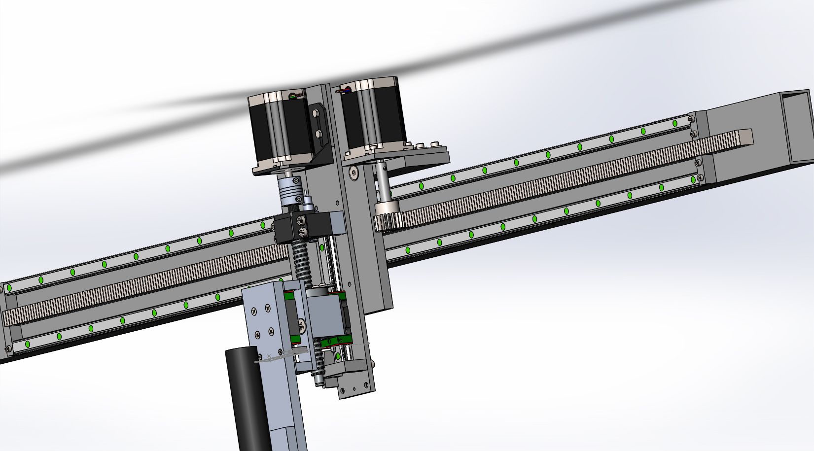
I remembered I had a spare FF12 bearing block which just has clearance with the linear rail. So here is the revised design following Todd's advice.
I know the bearing block is a floating one, but with a step in the shaft one side and a pinion on the other, there won't be any play. I'll probably need a small spacer or washer on the pinion side.
I know the bearing block is a floating one, but with a step in the shaft one side and a pinion on the other, there won't be any play. I'll probably need a small spacer or washer on the pinion side.
Please Log in or Create an account to join the conversation.
- andypugh
-

- Offline
- Moderator
-

Less
More
- Posts: 19848
- Thank you received: 4630
04 Sep 2016 11:02 - 04 Sep 2016 11:03 #80008
by andypugh
Replied by andypugh on topic Do you really need a spring loaded pinion drive?
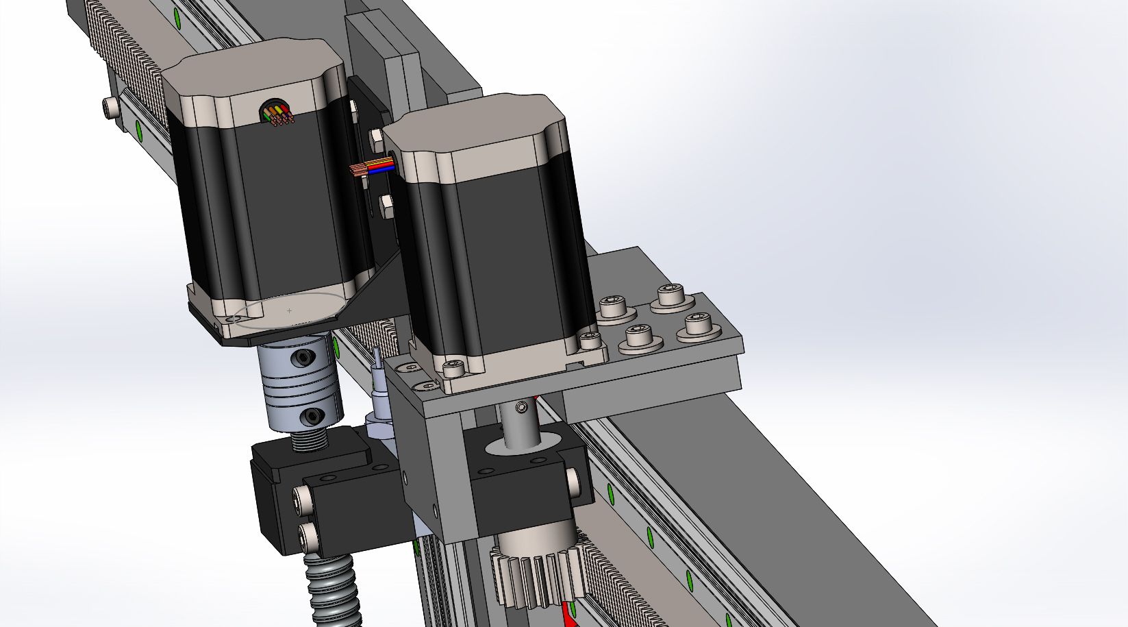
I had the same thoughts as Todd about the overhanging shaft, but my suggestion was going to be to move the motor mounting plate to the other side to get the motor as low as possible and to move the rack itself up as high as possible.
I would be looking for ways to reduce the "stack height" of the spindle mount too, to get the spindle closer to the linear rail. But I don't actually have any evidence that that is important, it's an opinion based on intuition, and intuition is often wrong.
But, you can spend an indefinite time optimising a design. I am half-way through designing (in my head) a one-piece aluminium casting for your carriage, with eccentric mountings to adjust engagement depth, and wondering if cast iron or magnesium would be better.
So, just build it, it seems like quite a low-powered spindle so the capability to machine Inconel probably isn't on your list.
Last edit: 04 Sep 2016 11:03 by andypugh.
Please Log in or Create an account to join the conversation.
- rodw
-
Topic Author
- Offline
- Platinum Member
-
Less
More
- Posts: 11854
- Thank you received: 4019
04 Sep 2016 13:06 #80016
by rodw
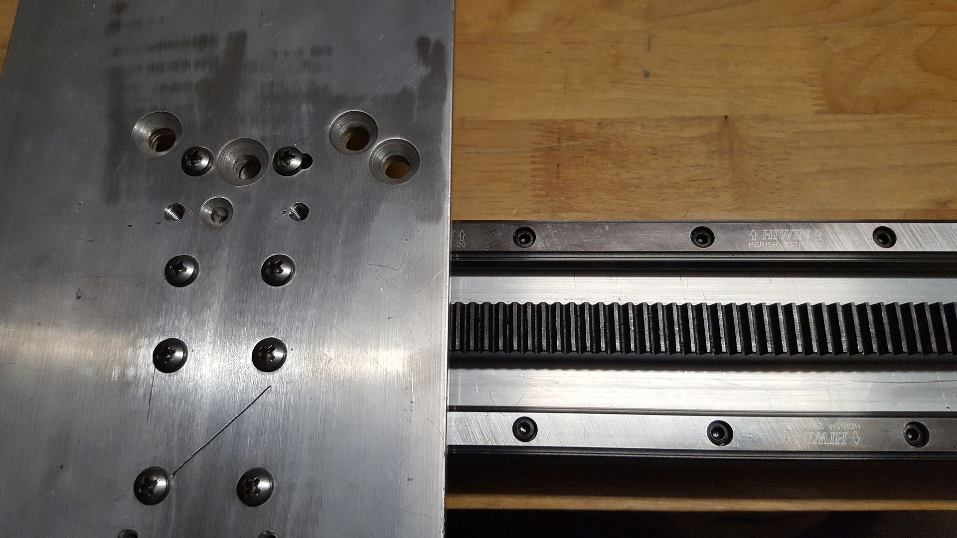
Andy, I love your advice. Kinda has a Nike flavour! I tried exactly that yesterday but ran into problems due to my inability to read my own drawings so stuck a couple of M8 countersunk holes in the wrong place. This became a very powerful incentive to learn how to create polar coordinates which are a lot easier to read!
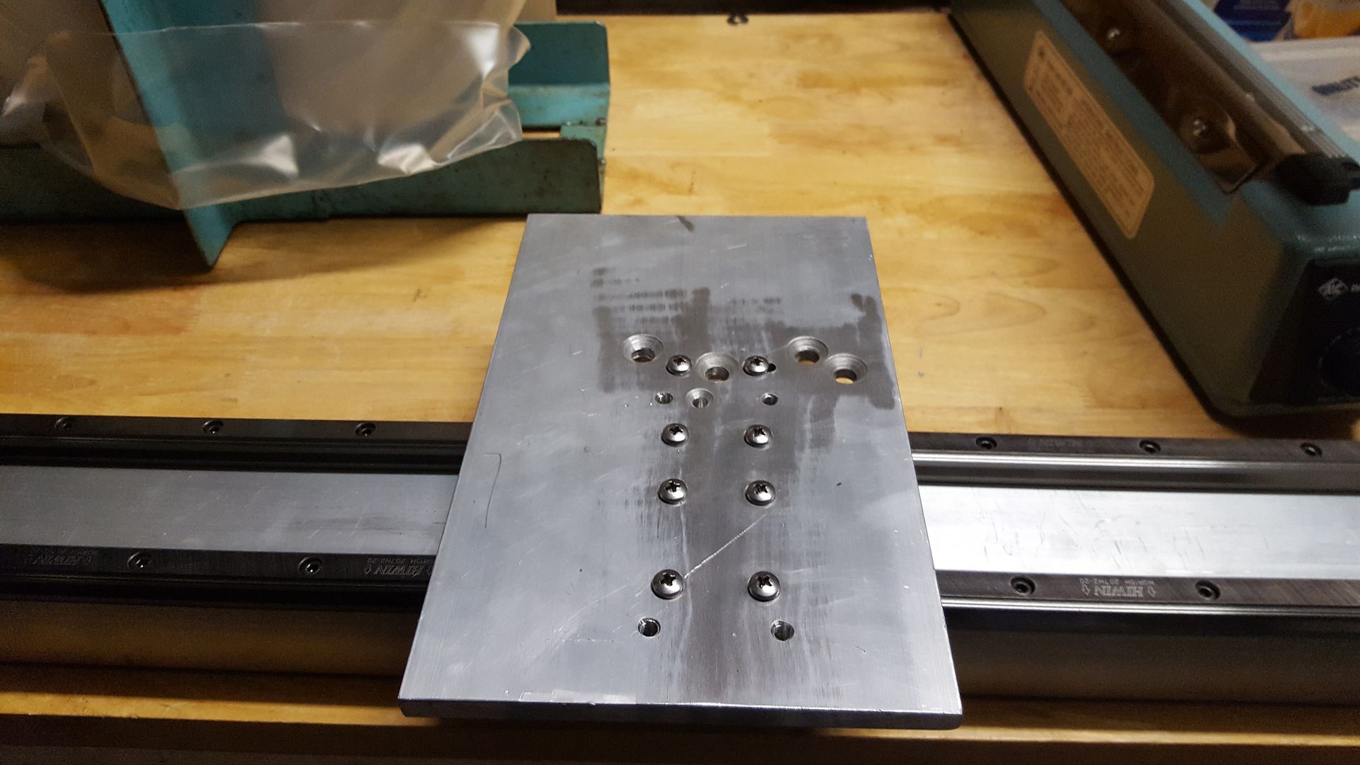
I could have worked around this. All bar one hole would be hidden once I put it together but I decided I will remake the part. Dealing with a 180mm wide plate in a mill with only 140mm Y axis travel is not without issues so I decided I'd make some clamping stuff for the mill before trying again. I'm only part way through that but I did cut stock for all parts I need to make so hopefully next weekend, there will be some serious progress!
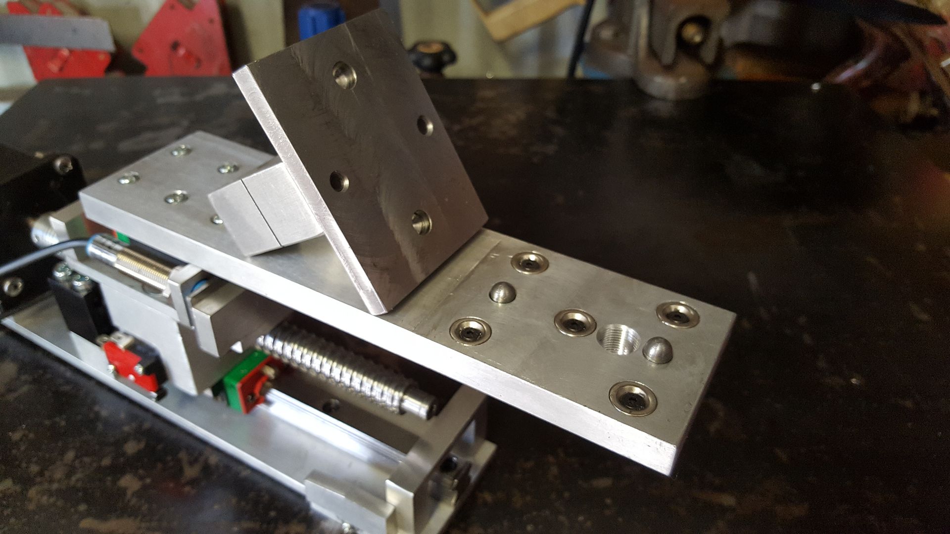
There are an enormous number of constraints with designing this. Believe it or not, I drew up designs with the rack mounted on top and the bottom of the crossmember before settling on the front mount between the rails version shown above. (Rack is just sitting in position and not mounted yet and still need to get some M4 countersunk screws to mount the plate to the carriages.
Originally, I had the torch mounted right on the ballscrew collar but decided if I put it lower, I would be able to design a cover to keep the muck out of the mechanics. There is room for an air scribe and maybe a web cam or laser pointer.
I made the deliberate decision to build solely for a plasma machine so yes, I won't be doing any milling. or routing.
The Z Axis is built
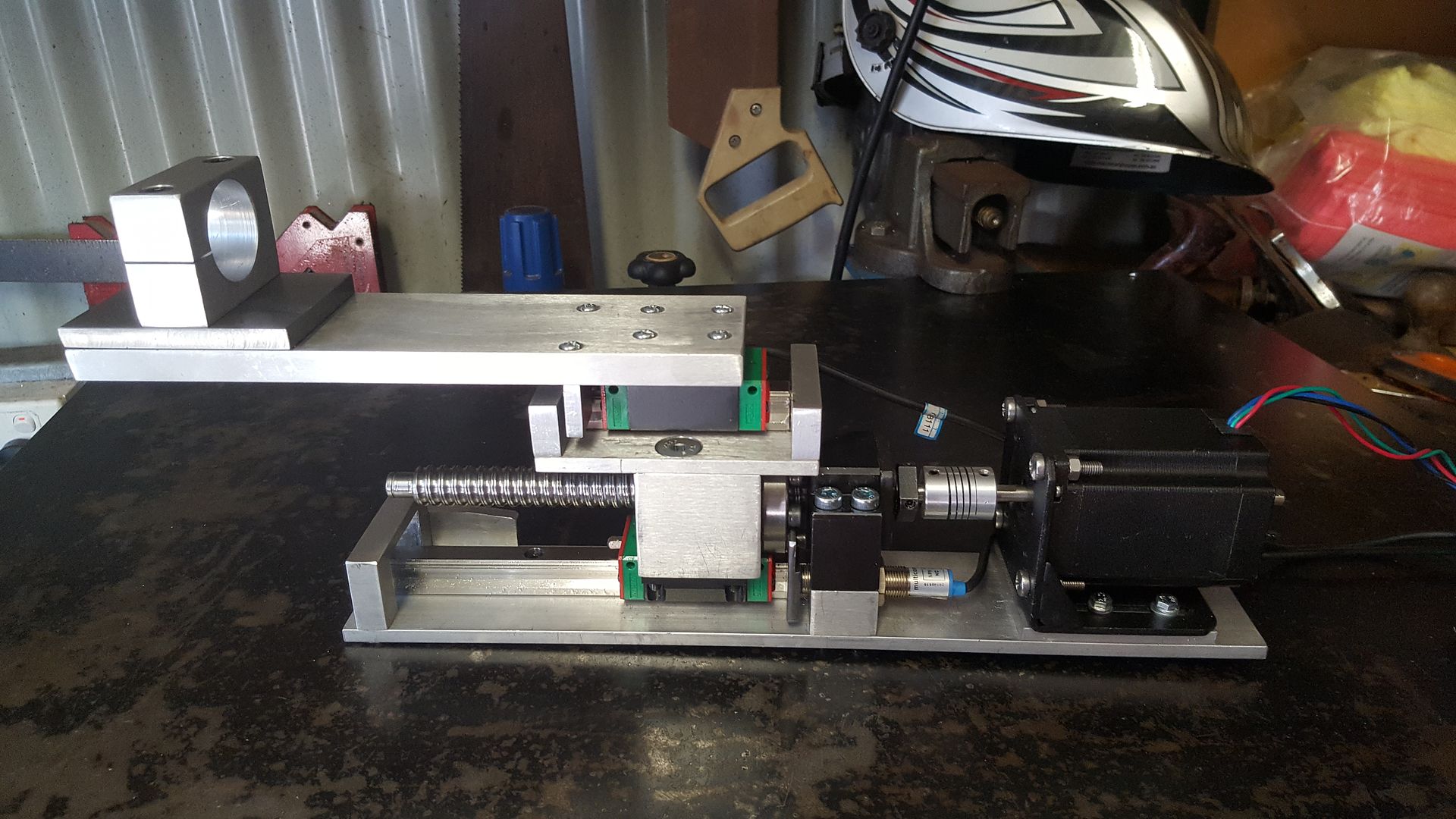
Complete with a magnetic breakaway
So I only have about 4 parts to get done to have a full working Z and Y axis. After that I want to build the electronics before building the table as it will take up a fair bit of room.
So now I've ticked off all the design stuff, I'm just gunna build it")
Replied by rodw on topic Do you really need a spring loaded pinion drive?
So, just build it, it seems like quite a low-powered spindle so the capability to machine Inconel probably isn't on your list.
Andy, I love your advice. Kinda has a Nike flavour! I tried exactly that yesterday but ran into problems due to my inability to read my own drawings so stuck a couple of M8 countersunk holes in the wrong place. This became a very powerful incentive to learn how to create polar coordinates which are a lot easier to read!
I could have worked around this. All bar one hole would be hidden once I put it together but I decided I will remake the part. Dealing with a 180mm wide plate in a mill with only 140mm Y axis travel is not without issues so I decided I'd make some clamping stuff for the mill before trying again. I'm only part way through that but I did cut stock for all parts I need to make so hopefully next weekend, there will be some serious progress!
There are an enormous number of constraints with designing this. Believe it or not, I drew up designs with the rack mounted on top and the bottom of the crossmember before settling on the front mount between the rails version shown above. (Rack is just sitting in position and not mounted yet and still need to get some M4 countersunk screws to mount the plate to the carriages.
Originally, I had the torch mounted right on the ballscrew collar but decided if I put it lower, I would be able to design a cover to keep the muck out of the mechanics. There is room for an air scribe and maybe a web cam or laser pointer.
I made the deliberate decision to build solely for a plasma machine so yes, I won't be doing any milling. or routing.
The Z Axis is built
Complete with a magnetic breakaway
So I only have about 4 parts to get done to have a full working Z and Y axis. After that I want to build the electronics before building the table as it will take up a fair bit of room.
So now I've ticked off all the design stuff, I'm just gunna build it
Please Log in or Create an account to join the conversation.
Time to create page: 0.284 seconds