Search Results (Searched for: stepper spindle)
- schorsch
- schorsch
12 Feb 2025 19:51
Using A axis as second spindle with stepper motor was created by schorsch
Using A axis as second spindle with stepper motor
Category: Advanced Configuration
Hi,
I'm using linuxcnc since a while. I upgraded a few weeks ago: Now I'm using a Rpi and a MESA 7C81. I'm having 3 axis and a fixed vertical spindle motor and a separated a-axis. All 4 axes are running with stepper motors.
I'm using inventor-hsm for creating G-code which works pretty good. Unfortunately, it is very limited, when using it in connection with the A-axis. Although the software is able to unwrap a geometry I can only run it to mill out closed pocked (also when it is wrapped). Very frequently I need to reduce a diameter and there is no operation available for this. I can only do this in indexed mode (several phi-angles and slicing in z).
Luckily the software can also produce code for turning machines, so I could create code for such a machine. The only thing I need to do is to turn on a horizontal spindle, you see my idea?
So my question:
Is there a possibility to configure linuxcnc in such a way that I can use my A-stepper axis for running as horizontal spindle?
What I need is a G-command turning the horizontal spindle on in a certain speed and a G-command for turning it of, during the turn-on the stepper needs to run continuously. I know its a bit absurd
Georg
- rodw

11 Feb 2025 20:32
Replied by rodw on topic Mesa with Ethercad connection
Mesa with Ethercad connection
Category: Driver Boards
As the OP said, the missing piece in an Ethercat build is affordable encoder inputs for spindles. There are very few options outside of Beckhoff. I have some Beckhoff I/O but have not bought an encoder module.
There are a few I/O modules generally with 16 inputs and 16 outputs. There must be a cheap Ethercat chip they use. Examples from Deiwu and Rtelligent (I have both). Rtelligent includes some PWM outputs.
But lets face it, the main reason one goes with Ethercat is to use Ethercat servo and stepper drives so the Mesa cards with analog and step/dir interfaces are not particularly useful any more.
Using Ethercat drives reduces the need for I/O because most drives have some included I/O for home and limit switches and brakes etc. These can also be used for general I/O.
Whilst using hm2 over Ethercat should improve network latency issues with Mesa cards due to the more efficient transport layer, adding the additional complexity of Ethercat just for this does not make sense to me.
Perhaps Mesa could look at an Ethercat 7i92 equivalent that supported some existing daughter cards to give I/O, encoder, counters for MPG and analog voltage by adding a THCAD2 with its Calibration data stored in Ethercat registers? Perhaps this card would include some smart serial interfaces too?
Anyway, I'm gonna go back to fiddling with Ethercat internal homing now... After a long hiatus, I got my homing lab working last night and homing commenced as it should. I just have to work out why it didn't respond to the homing switch when it came on...
- Esz2
- Esz2
09 Feb 2025 19:11
From Grbl to linuxcnc was created by Esz2
From Grbl to linuxcnc
Category: General LinuxCNC Questions
Im an electronics technician located in Denmark with an hobby interest in mechanical design, cnc milling and additive manufacturing.
A couple of years ago I bought an cnc router with zero experience in the field. The building and electrical parts where a breeze and the grbl controller that I bought back then was an easy thing to flash with fluidNC and get going.
Now I'm going into more advanced features and adding an self designed atc system hereby arose the need for a more capable controller. The choice settled on the Mesanet 7c80 due to form factor with the rpi and the number of i/o without the need for an daughterboard.
I have experience with rpi/arduino/esp32 projects and have worked a limited bit with commercial fpga cards before.
I have never worked with Linuxcnc before but settled on this environment and the mesa board due to:
1. active community
2. Full customization
So the big question is, where do I begin? What would be a good course of action to get going in an orderly manner?
The hardware:
clossed loop steppers and drivers
XYYZ + AB (possible used to manipulated the ATC later)
inductive sensors on all axis
several solunoidvalves (mist and air)
several relays (pumps and spindle light)
surface probe
tool lenght sensor
several failsafe and e-stops
ballscrews on all axis
The atc system will be an add on later and will not be a part of the initial setup.
The electrical part is going to be an non issue for me I have already planned this from the drawings in the 7c80 manual.
Thanks in advance
- Lisov_R
- Lisov_R
07 Feb 2025 01:44
Replied by Lisov_R on topic ColorCNC Colorlight 5A-75E/5A-75B as FPGA controller board
ColorCNC Colorlight 5A-75E/5A-75B as FPGA controller board
Category: Driver Boards
I am attaching all the files of my 5-axis machine with the ability to work only with stepper motors, motors and an ecoder and in ClosedLoop mode. Spindle control via RS485 with a frequency converter. Additionally, the xhc-hb04 remote control is connected.
- Meichinger
- Meichinger
04 Feb 2025 20:23
systematic drift on arcs was created by Meichinger
systematic drift on arcs
Category: General LinuxCNC Questions
Hi Linux CNC forum,
I'm building on a small CNC for over two years now. Unfortunately, I've been running in some issues while milling circular pockets.
machine specs:
Traj XYZA
y-axis 1190 mm max travel, 20 mm ballscrew with 10 mm pitch, two 750W AC servo (HLTNC)
x-axis 900 mm max travel, 20 mm ballscrew with 10 mm pitch, one 750W AC servo (HLTNC)
z-axis 185 mm max travel, 16 mm ballscrew with 5 mm pitch, high torque nema 34 stepper
spindle - 2,2 kw rattmotor air cooled
Brain of the operation: raspberry pi 4b+ using a parallel port hat and a 5 axis breakout board
I'm running the premanufactured PI4 optimized Debian Bookworm image.
Y-axis settings as follows:
max_velocity = 5000 mm/min
max_acc = 20000 mm/min2
min limit = 0 mm
max limit = 1190 mm
stepgen_maxaccel = 40000
scale = 10 steps/mm -> (not sure why i set this to 10 -> 200 steps/rev and 10 mm pitch shall result in 20 steps/mm)
FERROR = 1
Min_Ferror = 0.25
The issue:
See attachment for further details
arcs/circular shapes are for any reason shifted in XY - direction, the error occurs above 250 mm/min and is almost unchanged between 1000-5000 mm/min.
What did i test up to now:
Any hint or recommendation on how to improve this would be appreciated!
Thank you!
Michael
I'm building on a small CNC for over two years now. Unfortunately, I've been running in some issues while milling circular pockets.
machine specs:
Traj XYZA
y-axis 1190 mm max travel, 20 mm ballscrew with 10 mm pitch, two 750W AC servo (HLTNC)
x-axis 900 mm max travel, 20 mm ballscrew with 10 mm pitch, one 750W AC servo (HLTNC)
z-axis 185 mm max travel, 16 mm ballscrew with 5 mm pitch, high torque nema 34 stepper
spindle - 2,2 kw rattmotor air cooled
Brain of the operation: raspberry pi 4b+ using a parallel port hat and a 5 axis breakout board
I'm running the premanufactured PI4 optimized Debian Bookworm image.
Y-axis settings as follows:
max_velocity = 5000 mm/min
max_acc = 20000 mm/min2
min limit = 0 mm
max limit = 1190 mm
stepgen_maxaccel = 40000
scale = 10 steps/mm -> (not sure why i set this to 10 -> 200 steps/rev and 10 mm pitch shall result in 20 steps/mm)
FERROR = 1
Min_Ferror = 0.25
The issue:
See attachment for further details
arcs/circular shapes are for any reason shifted in XY - direction, the error occurs above 250 mm/min and is almost unchanged between 1000-5000 mm/min.
What did i test up to now:
- Change base_period up and down -> the servos are set to 200 "steps"/rev, 10 mm pitch -> thus 20 steps/mm resulting in below 2000 pulses per second on one axis. Base_period is set to 100k, shall be fine? Changing the base_period to 40k didn't change anything as well as increasing the base period to 150k.
- Change max_acc to 4x max_velocity and stepgen to 2x max_acc -> didn't change anything
- check mechanical stiffness and backlash -> everything feels tight and rock solid, the linear guide rails are 20x30mm using very massiv long carriers.
- kill all unnecessary PIDs on the debain system in order to reduce latency -> didn't change anything
Any hint or recommendation on how to improve this would be appreciated!
Thank you!
Michael
- jtrantow
- jtrantow
03 Feb 2025 23:01 - 03 Feb 2025 23:03
PWM with a 7i96 and 7i85 was created by jtrantow
PWM with a 7i96 and 7i85
Category: General LinuxCNC Questions
I'm running a 7i96 with a 7i85 for my lathe(steppers and linear encoders) using 7i96_7i85ssdid.bit I have been using LCNC pwmgen and I'd like to switch to the Mesa pwmgen before I spend time tuning the spindle VFD pid further. (I use the stepgen.00.index-enable pin for homing)
I loadrt [HM2](DRIVER) board_ip=[HM2](ADDRESS) config="num_encoders=3 num_pwmgens=1 num_stepgens=4 sserial_port_0=00xxxx" I'm using TB3 ENC 0, ENC 1, ENC2 on the 7i85 and TB1 STEP 0, STEP 1, STEP 2, STEP 3 on the 7i96.This all works with the LCNC pwmgen driving ssr.00.out-02.
I added the mesa pwmgen and I can run the mesa pwmgen in parallel but I can't find the pwmgen signal coming out the Mesa board.
I was expecting to see the PWM output on the TB2 STEP4 (TB2-02, TP2-03) connector but I do not see a PWM gen signal?
7i96_7i85ssdid.pin from readhmid reports there is a PWM module in the firmware (and I can see the pwmgen pins in HALMeter and HALShow) but I can't figure out the pwm signal connector?
LCNCpins.txt doesn't show the PWM assignment either?
LatheSpindle.hal has my relevant HAL connections.
Any help would be appreciated.
- RNJFAB
- RNJFAB
02 Feb 2025 04:57 - 02 Feb 2025 07:01
Replied by RNJFAB on topic Homemade CNC Plasma - hypertherm, Mesa, gear drives, nema 34.
Homemade CNC Plasma - hypertherm, Mesa, gear drives, nema 34.
Category: Show Your Stuff
not sure about debouncing on the limit switches.
Mesa 7i96,THCAD10, closed loop nema34. hypertherm xp45 with cpc port.
all fixed with the 24v field power. thanks Rod.
next problem is the thc is not reading. I have checked the THC with 9V battery and it works there, so guessing the problem lies in my INI or HAL files.
# Generated by PNCconf at Sun Feb 2 06:15:46 2025
# Using LinuxCNC version: Master (2.9)
# If you make changes to this file, they will be
# overwritten when you run PNCconf again
[EMC]
MACHINE = T17
DEBUG = 0
VERSION = 1.1
[DISPLAY]
DISPLAY = qtvcp qtplasmac
POSITION_OFFSET = RELATIVE
POSITION_FEEDBACK = ACTUAL
MAX_FEED_OVERRIDE = 2.000000
INTRO_GRAPHIC = linuxcnc.gif
INTRO_TIME = 5
PROGRAM_PREFIX = /home/cnc/linuxcnc/nc_files
INCREMENTS = 10mm 1mm 100mm
POSITION_FEEDBACK = ACTUAL
DEFAULT_LINEAR_VELOCITY = 83.333333
MAX_LINEAR_VELOCITY = 183.333333
MIN_LINEAR_VELOCITY = 1.666667
DEFAULT_ANGULAR_VELOCITY = 12.000000
MAX_ANGULAR_VELOCITY = 180.000000
MIN_ANGULAR_VELOCITY = 1.666667
GEOMETRY = xyz
CYCLE_TIME = 100
[FILTER]
PROGRAM_EXTENSION = .ngc,.nc,.tap GCode File (*.ngc, *.nc, *.tap)
ngc = qtplasmac_gcode
nc = qtplasmac_gcode
tap = qtplasmac_gcode
[TASK]
TASK = milltask
CYCLE_TIME = 0.010
[RS274NGC]
PARAMETER_FILE = linuxcnc.var
RS274NGC_STARTUP_CODE = G21 G40 G49 G80 G90 G92.1 G94 G97 M52P1
SUBROUTINE_PATH = ./:../../nc_files
USER_M_PATH = ./:../../nc_files
[EMCMOT]
EMCMOT = motmod
COMM_TIMEOUT = 1.0
SERVO_PERIOD = 1000000
[HMOT]
CARD0=hm2_7i96.0
[HAL]
HALUI = halui
HALFILE = T17.hal
HALFILE = qtplasmac_comp.hal
HALFILE = custom.hal
POSTGUI_HALFILE = custom_postgui.hal
SHUTDOWN = shutdown.hal
[HALUI]
[KINS]
JOINTS = 4
KINEMATICS = trivkins coordinates=XYYZ
[TRAJ]
SPINDLES = 3
COORDINATES = XYYZ
LINEAR_UNITS = mm
ANGULAR_UNITS = degree
DEFAULT_LINEAR_VELOCITY = 18.33
MAX_LINEAR_VELOCITY = 183.33
NO_FORCE_HOMING = 1
[EMCIO]
EMCIO = io
CYCLE_TIME = 0.100
TOOL_TABLE = tool.tbl
#******************************************
[AXIS_X]
# MAX_VEL & MAX_ACC need to be twice the corresponding joint value
MAX_VELOCITY = 366.6666666666667
MAX_ACCELERATION = 4000.0
OFFSET_AV_RATIO = 0.5
MIN_LIMIT = -5.0
MAX_LIMIT = 1300.0
[JOINT_0]
TYPE = LINEAR
HOME = 10.0
FERROR = 10.0
MIN_FERROR = 1.0
MAX_VELOCITY = 183.33333333333334
MAX_ACCELERATION = 2000.0
# The values below should be 25% larger than MAX_VELOCITY and MAX_ACCELERATION
# If using BACKLASH compensation STEPGEN_MAXACCEL should be 100% larger.
STEPGEN_MAXVEL = 229.17
STEPGEN_MAXACCEL = 2500.00
P = 1000.0
I = 0.0
D = 0.0
FF0 = 0.0
FF1 = 1.0
FF2 = 0.0
BIAS = 0.0
DEADBAND = 0.0
MAX_OUTPUT = 0.0
# these are in nanoseconds
DIRSETUP = 10000
DIRHOLD = 10000
STEPLEN = 5000
STEPSPACE = 5000
STEP_SCALE = 52.0833
MIN_LIMIT = -5.0
MAX_LIMIT = 1300.0
HOME_OFFSET = -10.000000
HOME_SEARCH_VEL = -50.000000
HOME_LATCH_VEL = -25.000000
HOME_FINAL_VEL = 16.666667
HOME_USE_INDEX = NO
HOME_IGNORE_LIMITS = YES
HOME_SEQUENCE = 1
#******************************************
#******************************************
[AXIS_Y]
# MAX_VEL & MAX_ACC need to be twice the corresponding joint value
MAX_VELOCITY = 366.6666666666667
MAX_ACCELERATION = 5000.0
OFFSET_AV_RATIO = 0.5
MIN_LIMIT = -5.0
MAX_LIMIT = 2520.0
[JOINT_1]
TYPE = LINEAR
HOME = 10.0
FERROR = 10.0
MIN_FERROR = 1.0
MAX_VELOCITY = 183.33333333333334
MAX_ACCELERATION = 2500.0
# The values below should be 25% larger than MAX_VELOCITY and MAX_ACCELERATION
# If using BACKLASH compensation STEPGEN_MAXACCEL should be 100% larger.
STEPGEN_MAXVEL = 229.17
STEPGEN_MAXACCEL = 3125.00
P = 1000.0
I = 0.0
D = 0.0
FF0 = 0.0
FF1 = 1.0
FF2 = 0.0
BIAS = 0.0
DEADBAND = 0.0
MAX_OUTPUT = 0.0
# these are in nanoseconds
DIRSETUP = 10000
DIRHOLD = 10000
STEPLEN = 5000
STEPSPACE = 5000
STEP_SCALE = 52.0833
MIN_LIMIT = -5.0
MAX_LIMIT = 2520.0
HOME_OFFSET = -10.000000
HOME_SEARCH_VEL = -50.000000
HOME_LATCH_VEL = -25.000000
HOME_FINAL_VEL = 16.666667
HOME_USE_INDEX = NO
HOME_IGNORE_LIMITS = YES
HOME_SEQUENCE = -2
[JOINT_2]
TYPE = LINEAR
HOME = 10.0
FERROR = 10.0
MIN_FERROR = 1.0
MAX_VELOCITY = 183.33333333333334
MAX_ACCELERATION = 2500.0
# The values below should be 25% larger than MAX_VELOCITY and MAX_ACCELERATION
# If using BACKLASH compensation STEPGEN_MAXACCEL should be 100% larger.
STEPGEN_MAXVEL = 229.17
STEPGEN_MAXACCEL = 3125.00
P = 1000.0
I = 0.0
D = 0.0
FF0 = 0.0
FF1 = 1.0
FF2 = 0.0
BIAS = 0.0
DEADBAND = 0.0
MAX_OUTPUT = 0.0
# these are in nanoseconds
DIRSETUP = 10000
DIRHOLD = 10000
STEPLEN = 5000
STEPSPACE = 5000
STEP_SCALE = 52.0833
MIN_LIMIT = -5.0
MAX_LIMIT = 2520.0
HOME_OFFSET = -10.000000
HOME_SEARCH_VEL = -50.000000
HOME_LATCH_VEL = -25.000000
HOME_FINAL_VEL = 16.666667
HOME_USE_INDEX = NO
HOME_IGNORE_LIMITS = YES
HOME_SEQUENCE = -2
#******************************************
#******************************************
[AXIS_Z]
# MAX_VEL & MAX_ACC need to be twice the corresponding joint value
MAX_VELOCITY = 66.66666666666667
MAX_ACCELERATION = 400.0
OFFSET_AV_RATIO = 0.5
MIN_LIMIT = -150.0
MAX_LIMIT = 5.0
[JOINT_3]
TYPE = LINEAR
HOME = -10.0
FERROR = 10.0
MIN_FERROR = 1.0
MAX_VELOCITY = 33.333333333333336
MAX_ACCELERATION = 200.0
# The values below should be 25% larger than MAX_VELOCITY and MAX_ACCELERATION
# If using BACKLASH compensation STEPGEN_MAXACCEL should be 100% larger.
STEPGEN_MAXVEL = 41.67
STEPGEN_MAXACCEL = 250.00
P = 1000.0
I = 0.0
D = 0.0
FF0 = 0.0
FF1 = 1.0
FF2 = 0.0
BIAS = 0.0
DEADBAND = 0.0
MAX_OUTPUT = 0.0
# these are in nanoseconds
DIRSETUP = 10000
DIRHOLD = 10000
STEPLEN = 5000
STEPSPACE = 5000
STEP_SCALE = 392.1569
MIN_LIMIT = -150.0
MAX_LIMIT = 5.0
HOME_OFFSET = 5.000000
HOME_SEARCH_VEL = 8.333333
HOME_LATCH_VEL = 8.333333
HOME_FINAL_VEL = -8.333333
HOME_USE_INDEX = NO
HOME_IGNORE_LIMITS = YES
HOME_SEQUENCE = 1
#******************************************
# Generated by PNCconf at Sun Jan 26 20:35:25 2025
# Using LinuxCNC version: Master (2.9)
# If you make changes to this file, they will be
# overwritten when you run PNCconf again
loadrt [KINS]KINEMATICS
loadrt [EMCMOT]EMCMOT servo_period_nsec=[EMCMOT]SERVO_PERIOD num_joints=[KINS]JOINTS num_spindles=[TRAJ]SPINDLES
loadrt hostmot2
loadrt hm2_eth board_ip="10.10.10.10" config="num_encoders=1 num_pwmgens=0 num_stepgens=5 sserial_port_0=0xxxxxxx"
setp [HMOT](CARD0).watchdog.timeout_ns 5000000
loadrt pid names=pid.x,pid.y,pid.y2,pid.z,pid.s
loadrt plasmac
addf [HMOT](CARD0).read servo-thread
addf motion-command-handler servo-thread
addf motion-controller servo-thread
addf pid.x.do-pid-calcs servo-thread
addf pid.y.do-pid-calcs servo-thread
addf pid.y2.do-pid-calcs servo-thread
addf pid.z.do-pid-calcs servo-thread
addf pid.s.do-pid-calcs servo-thread
addf plasmac servo-thread
addf [HMOT](CARD0).write servo-thread
setp [HMOT](CARD0).dpll.01.timer-us -50
setp [HMOT](CARD0).stepgen.timer-number 1
# ---PLASMA INPUT DEBOUNCE---
#values for these are in custom.hal
loadrt dbounce names=db_breakaway,db_float,db_ohmic,db_arc-ok
addf db_float servo-thread
addf db_ohmic servo-thread
addf db_breakaway servo-thread
addf db_arc-ok servo-thread
# ---JOINT ASSOCIATED WITH THE Z AXIS---
net plasmac:axis-position joint.3.pos-fb => plasmac.axis-z-position
# ---PLASMA INPUTS---
# ---all modes---
net plasmac:float-switch => db_float.in
net plasmac:breakaway => db_breakaway.in
net plasmac:ohmic-probe => db_ohmic.in
net plasmac:ohmic-sense-in => plasmac.ohmic-sense-in
# ---modes 0 & 1
net plasmac:arc-voltage-in => plasmac.arc-voltage-in
# ---modes 1 & 2
net plasmac:arc-ok-in => db_arc-ok.in
# ---mode 2
net plasmac:move-up <= plasmac.move-up
net plasmac:move-down <= plasmac.move-down
# ---PLASMA OUTPUTS---
# ---all modes---
net plasmac:ohmic-enable <= plasmac.ohmic-enable
net plasmac:scribe-arm <= plasmac.scribe-arm
net plasmac:scribe-on <= plasmac.scribe-on
# external output signals
# --- PLASMAC:TORCH-ON ---
net plasmac:torch-on => [HMOT](CARD0).ssr.00.out-00
# external input signals
# --- ESTOP-EXT ---
net estop-ext <= [HMOT](CARD0).gpio.000.in_not
# --- BOTH-HOME-X ---
net both-home-x <= [HMOT](CARD0).gpio.001.in_not
# --- BOTH-HOME-Y ---
net both-home-y <= [HMOT](CARD0).gpio.002.in_not
# --- BOTH-HOME-Y2 ---
net both-home-y2 <= [HMOT](CARD0).gpio.003.in_not
# --- BOTH-HOME-Z ---
net both-home-z <= [HMOT](CARD0).gpio.004.in_not
# --- PLASMAC:FLOAT-SWITCH ---
net plasmac:float-switch <= [HMOT](CARD0).gpio.005.in_not
# --- PLASMAC:BREAKAWAY ---
net plasmac:breakaway <= [HMOT](CARD0).gpio.006.in_not
# --- Encoder ---
#*******************
# AXIS X JOINT 0
#*******************
setp pid.x.Pgain [JOINT_0]P
setp pid.x.Igain [JOINT_0]I
setp pid.x.Dgain [JOINT_0]D
setp pid.x.bias [JOINT_0]BIAS
setp pid.x.FF0 [JOINT_0]FF0
setp pid.x.FF1 [JOINT_0]FF1
setp pid.x.FF2 [JOINT_0]FF2
setp pid.x.deadband [JOINT_0]DEADBAND
setp pid.x.maxoutput [JOINT_0]MAX_OUTPUT
setp pid.x.error-previous-target true
# This setting is to limit bogus stepgen
# velocity corrections caused by position
# feedback sample time jitter.
setp pid.x.maxerror 0.012700
net x-index-enable => pid.x.index-enable
net x-enable => pid.x.enable
net x-pos-cmd => pid.x.command
net x-pos-fb => pid.x.feedback
net x-output <= pid.x.output
# Step Gen signals/setup
setp [HMOT](CARD0).stepgen.01.dirsetup [JOINT_0]DIRSETUP
setp [HMOT](CARD0).stepgen.01.dirhold [JOINT_0]DIRHOLD
setp [HMOT](CARD0).stepgen.01.steplen [JOINT_0]STEPLEN
setp [HMOT](CARD0).stepgen.01.stepspace [JOINT_0]STEPSPACE
setp [HMOT](CARD0).stepgen.01.position-scale [JOINT_0]STEP_SCALE
setp [HMOT](CARD0).stepgen.01.step_type 0
setp [HMOT](CARD0).stepgen.01.control-type 1
setp [HMOT](CARD0).stepgen.01.maxaccel [JOINT_0]STEPGEN_MAXACCEL
setp [HMOT](CARD0).stepgen.01.maxvel [JOINT_0]STEPGEN_MAXVEL
# ---closedloop stepper signals---
net x-pos-cmd <= joint.0.motor-pos-cmd
net x-vel-cmd <= joint.0.vel-cmd
net x-output => [HMOT](CARD0).stepgen.01.velocity-cmd
net x-pos-fb <= [HMOT](CARD0).stepgen.01.position-fb
net x-pos-fb => joint.0.motor-pos-fb
net x-enable <= joint.0.amp-enable-out
net x-enable => [HMOT](CARD0).stepgen.01.enable
# ---setup home / limit switch signals---
net both-home-x => joint.0.home-sw-in
net both-home-x => joint.0.neg-lim-sw-in
net both-home-x => joint.0.pos-lim-sw-in
#*******************
# AXIS Y JOINT 1
#*******************
setp pid.y.Pgain [JOINT_1]P
setp pid.y.Igain [JOINT_1]I
setp pid.y.Dgain [JOINT_1]D
setp pid.y.bias [JOINT_1]BIAS
setp pid.y.FF0 [JOINT_1]FF0
setp pid.y.FF1 [JOINT_1]FF1
setp pid.y.FF2 [JOINT_1]FF2
setp pid.y.deadband [JOINT_1]DEADBAND
setp pid.y.maxoutput [JOINT_1]MAX_OUTPUT
setp pid.y.error-previous-target true
# This setting is to limit bogus stepgen
# velocity corrections caused by position
# feedback sample time jitter.
setp pid.y.maxerror 0.012700
net y-index-enable => pid.y.index-enable
net y-enable => pid.y.enable
net y-pos-cmd => pid.y.command
net y-pos-fb => pid.y.feedback
net y-output <= pid.y.output
# Step Gen signals/setup
setp [HMOT](CARD0).stepgen.03.dirsetup [JOINT_1]DIRSETUP
setp [HMOT](CARD0).stepgen.03.dirhold [JOINT_1]DIRHOLD
setp [HMOT](CARD0).stepgen.03.steplen [JOINT_1]STEPLEN
setp [HMOT](CARD0).stepgen.03.stepspace [JOINT_1]STEPSPACE
setp [HMOT](CARD0).stepgen.03.position-scale [JOINT_1]STEP_SCALE
setp [HMOT](CARD0).stepgen.03.step_type 0
setp [HMOT](CARD0).stepgen.03.control-type 1
setp [HMOT](CARD0).stepgen.03.maxaccel [JOINT_1]STEPGEN_MAXACCEL
setp [HMOT](CARD0).stepgen.03.maxvel [JOINT_1]STEPGEN_MAXVEL
# ---closedloop stepper signals---
net y-pos-cmd <= joint.1.motor-pos-cmd
net y-vel-cmd <= joint.1.vel-cmd
net y-output => [HMOT](CARD0).stepgen.03.velocity-cmd
net y-pos-fb <= [HMOT](CARD0).stepgen.03.position-fb
net y-pos-fb => joint.1.motor-pos-fb
net y-enable <= joint.1.amp-enable-out
net y-enable => [HMOT](CARD0).stepgen.03.enable
# ---setup home / limit switch signals---
net both-home-y => joint.1.home-sw-in
net both-home-y => joint.1.neg-lim-sw-in
net both-home-y => joint.1.pos-lim-sw-in
#*******************
# Tandem AXIS Y2 JOINT 2
#*******************
setp pid.y2.Pgain [JOINT_2]P
setp pid.y2.Igain [JOINT_2]I
setp pid.y2.Dgain [JOINT_2]D
setp pid.y2.bias [JOINT_2]BIAS
setp pid.y2.FF0 [JOINT_2]FF0
setp pid.y2.FF1 [JOINT_2]FF1
setp pid.y2.FF2 [JOINT_2]FF2
setp pid.y2.deadband [JOINT_2]DEADBAND
setp pid.y2.maxoutput [JOINT_2]MAX_OUTPUT
setp pid.y2.error-previous-target true
# This setting is to limit bogus stepgen
# velocity corrections caused by position
# feedback sample time jitter.
setp pid.y2.maxerror 0.012700
net y2-index-enable => pid.y2.index-enable
net y2-enable => pid.y2.enable
net y2-pos-cmd => pid.y2.command
net y2-pos-fb => pid.y2.feedback
net y2-output <= pid.y2.output
# Step Gen signals/setup for tandem axis
setp [HMOT](CARD0).stepgen.02.dirsetup [JOINT_2]DIRSETUP
setp [HMOT](CARD0).stepgen.02.dirhold [JOINT_2]DIRHOLD
setp [HMOT](CARD0).stepgen.02.steplen [JOINT_2]STEPLEN
setp [HMOT](CARD0).stepgen.02.stepspace [JOINT_2]STEPSPACE
setp [HMOT](CARD0).stepgen.02.position-scale [JOINT_2]STEP_SCALE
setp [HMOT](CARD0).stepgen.02.step_type 0
setp [HMOT](CARD0).stepgen.02.control-type 1
setp [HMOT](CARD0).stepgen.02.maxaccel [JOINT_2]STEPGEN_MAXACCEL
setp [HMOT](CARD0).stepgen.02.maxvel [JOINT_2]STEPGEN_MAXVEL
# ---closedloop stepper signals---
net y2-pos-cmd <= joint.2.motor-pos-cmd
net y2-vel-cmd <= joint.2.vel-cmd
net y2-output => [HMOT](CARD0).stepgen.02.velocity-cmd
net y2-pos-fb <= [HMOT](CARD0).stepgen.02.position-fb
net y2-pos-fb => joint.2.motor-pos-fb
net y2-enable <= joint.2.amp-enable-out
net y2-enable => [HMOT](CARD0).stepgen.02.enable
# ---setup home / limit switch signals---
net both-home-y2 => joint.2.home-sw-in
net both-home-y2 => joint.2.neg-lim-sw-in
net both-home-y2 => joint.2.pos-lim-sw-in
#*******************
# AXIS Z JOINT 3
#*******************
setp pid.z.Pgain [JOINT_3]P
setp pid.z.Igain [JOINT_3]I
setp pid.z.Dgain [JOINT_3]D
setp pid.z.bias [JOINT_3]BIAS
setp pid.z.FF0 [JOINT_3]FF0
setp pid.z.FF1 [JOINT_3]FF1
setp pid.z.FF2 [JOINT_3]FF2
setp pid.z.deadband [JOINT_3]DEADBAND
setp pid.z.maxoutput [JOINT_3]MAX_OUTPUT
setp pid.z.error-previous-target true
# This setting is to limit bogus stepgen
# velocity corrections caused by position
# feedback sample time jitter.
setp pid.z.maxerror 0.012700
net z-index-enable => pid.z.index-enable
net z-enable => pid.z.enable
net z-pos-cmd => pid.z.command
net z-pos-fb => pid.z.feedback
net z-output <= pid.z.output
# Step Gen signals/setup
setp [HMOT](CARD0).stepgen.00.dirsetup [JOINT_3]DIRSETUP
setp [HMOT](CARD0).stepgen.00.dirhold [JOINT_3]DIRHOLD
setp [HMOT](CARD0).stepgen.00.steplen [JOINT_3]STEPLEN
setp [HMOT](CARD0).stepgen.00.stepspace [JOINT_3]STEPSPACE
setp [HMOT](CARD0).stepgen.00.position-scale [JOINT_3]STEP_SCALE
setp [HMOT](CARD0).stepgen.00.step_type 0
setp [HMOT](CARD0).stepgen.00.control-type 1
setp [HMOT](CARD0).stepgen.00.maxaccel [JOINT_3]STEPGEN_MAXACCEL
setp [HMOT](CARD0).stepgen.00.maxvel [JOINT_3]STEPGEN_MAXVEL
# ---closedloop stepper signals---
net z-pos-cmd <= joint.3.motor-pos-cmd
net z-vel-cmd <= joint.3.vel-cmd
net z-output => [HMOT](CARD0).stepgen.00.velocity-cmd
net z-pos-fb <= [HMOT](CARD0).stepgen.00.position-fb
net z-pos-fb => joint.3.motor-pos-fb
net z-enable <= joint.3.amp-enable-out
net z-enable => [HMOT](CARD0).stepgen.00.enable
# ---setup home / limit switch signals---
net both-home-z => joint.3.home-sw-in
net both-home-z => joint.3.neg-lim-sw-in
net both-home-z => joint.3.pos-lim-sw-in
# ---motion control signals---
net in-position <= motion.in-position
net machine-is-enabled <= motion.motion-enabled
# ---digital in / out signals---
setp hm2_7i96.0.encoder.00.counter-mode 1
setp hm2_7i96.0.encoder.00.filter 1
setp hm2_7i96.0.encoder.00.scale -1
net plasmac:arc-voltage-in hm2_7i96.0.encoder.00.velocity => plasmac.arc-voltage-in
# ---estop signals---
net estop-out <= iocontrol.0.user-enable-out
net estop-ext => iocontrol.0.emc-enable-in
# ---QTPLASMAC TOOLCHANGE PASSTHROUGH---
net tool:change iocontrol.0.tool-change => iocontrol.0.tool-changed
net tool:prep iocontrol.0.tool-prepare => iocontrol.0.tool-prepared
# Include your custom HAL commands here
# This file will not be overwritten when you run PNCconf again
# ---COMMON PLASMAC DEBOUNCE---
# for the float and ohmic inputs each increment in delay is
# is a 0.001mm (0.00004") increase in any probed height result
setp db_float.delay 5
# set to zero if using internal ohmic sensing
setp db_ohmic.delay 0
setp db_breakaway.delay 5
setp db_arc-ok.delay 5
########################################
# The following variables are available for fine tuning some parameters.
# To use any of these, uncomment the required setp line and set an appropriate value.
# Dampen excessive noise on the arc voltage input
# default = 0 (volts)
#setp plasmac.lowpass-frequency 0
# The time delay from losing the arc ok signal until QtPlasmaC reacts to the arc loss.
# default = 0.0 (seconds)
#setp plasmac.arc-lost-delay 0.0
# For mode 0 Arc-OK only, the number of consecutive readings within the threshold that are required to set the Arc-OK signal.
# default = 6
#setp plasmac.arc-ok-counts 6
# For mode 0 Arc-OK only, the maximum voltage deviation that is allowed for a valid voltage to set the Arc OK signal.
#default = 10 (volts)
#setp plasmac.arc-ok-threshold 10
# The voltage above and below 0V that will display as 0V. Prevents small fluctuations from flickering the voltage display.
# default = 0 (volts)
#setp plasmac.zero-window 0
# The distance (in millimeters) away from the Z MAX_LIMIT that QtPlasmaC will allow the Z axis to travel while under machine control.
# default = 5 (mm)
#setp plasmac.max-offset 5
# The required number of consecutive times that the threshold has been exceeded before applying the void lock to the THC.
# default = 2
#setp plasmac.kerf-error-max 2
# ---OHMIC SENSE CONTACT DEBOUNCE---
setp plasmac.ohmic-sense-off-delay 3
setp plasmac.ohmic-sense-on-delay 3
- Taelman
- Taelman
01 Feb 2025 23:25
spindle setup was created by Taelman
spindle setup
Category: General LinuxCNC Questions
I want to connect my spindle to a 5 Axis Breakout Board Interface Adapter via a raspberry pi5. I can control the stepper motors (XYZ). I just can't control the spindle. Is there an example for the HAL file?
If I bypass the relay contact. Then the spindle will rotate to the maximum. If I press the + button it slows down. When I press the - button it speeds up. When I press the stop button, it starts running at maximum speed.
Anyone have a solution?
Greetings Philip
If I bypass the relay contact. Then the spindle will rotate to the maximum. If I press the + button it slows down. When I press the - button it speeds up. When I press the stop button, it starts running at maximum speed.
Anyone have a solution?
Greetings Philip
- Fianna

01 Feb 2025 21:58 - 01 Feb 2025 21:59
Digipot variability was created by Fianna
Digipot variability
Category: Driver Boards
Hi All,
Not a major issue, but my spindle speed is varying significantly under contant load. Sometimes during a cut and sometimes when it's just sitting and spinning up under no load and should be at constant speed. I'm not sure how much it varies because if I try to probe the pin the variance disappears, but audibly it slows down as if I ploughed it into a slightly too heavy cut that wasn't enough to stall the motor but enough to bog it down noticably.
My VFD (AT4 Aliexpress job) is driving a 3 Phase induction motor, 2.2kW, 2 pole.
The VFD has a 24v output but takes a 10v analog input, so I've just wired the 24v out to a simple voltage divider resistor pair (<5k total resistance) and I'm using that to feed the high side of the digipot on my 7i76e with 7v or therabouts. I tried using my 24v rail that supplies the limit switch, e-stop etc originally but the spindle speed was varying a lot (under constant load) so I assumed the VFD reference voltage and 24v rail might be too de-coupled and switched to using the VFD output thinking that would be a more consistent Vref for the VFD, but the spindle speed is still varying a lot.
My .ini file has got the SPINDLE_SCALE set to 8000 (It's an 8k RPM spindle), so I used M3 S8000 and then adjusted the vfd paramaters (P73) to get 60Hz, then checked at M3 S4000 and got roughtly 30Hz showing on the VFD screen so it seems to be working OK at max rpm and linear to within a few hundred RPM at 50%.
If I try to probe the voltage on the pin the impedance of the multimeter is enough to pull the VFD back to max RPM as soon as I probe it so I can't tell what the VFD vout or analog signal from the 7i76 is when a dip occurrs. My instinct is that the multimeter has some huge resistance in voltage mode and that a weak pullup / pulldown (1Meg?) would help, but I'm not sure so want to check to see if this is typical behaviour, I'm surprised that it doesn't 'just work'
On a separate (but potentially related?) note, I've got a significant AC voltage leakage to the machine frame ground, I'm not sure if this is the VFD itself or the SMPS which feed 72v to the stepper drivers, I need to do some un-plugging and checking. It's enough that you get a tingle if you touch the frame and you're grounded. I'm getting no DC voltage from machine frame to protective earth in the garage, but 20-60v AC showing on the multimeter. If I use current mode and check leakage current from machine frame to ground it immediately trips the RCD, so >>30mA. Not sure if this is an independant thing or if this leakage could be messing with the analog voltage signals.
Thoughs? Next steps? Independant things or related? What would you do next....
- timo
- timo
01 Feb 2025 09:59 - 03 Feb 2025 11:32
Stuck with spindle interface 7i76 card and weird BLDC driver was created by timo
Stuck with spindle interface 7i76 card and weird BLDC driver
Category: General LinuxCNC Questions
Hello,
I tried to figure that out, but not really successful, so I spam the forum with the questions. (I have the feeling I should have found the information somewhere; maybe someone can point me in the right direction)
I have a 6i25 card with a 7i76 card connected to my PC. Some stepper motors are running and can be moved with keyboard, a basic configuration is running.
Now I got stuck, trying to hook up the old BLDC driver (labeled TONMAN Brushless DC driver) or the machine (which I have no documentation for) seems not to run with an analog input.
I tried to connect the Spindle interface somehow, but it does not want to run.
There is a pair of pins labeled +- (PWM / ANNA), but I think it is not really for analog input signal.
Hooking up a potentiometer (allowing to create a voltage between 0 and 5V) does nothing to a certain voltage. At approx. 2.6V it switches from "off" to "full speed".
I tried one of those PWM generators
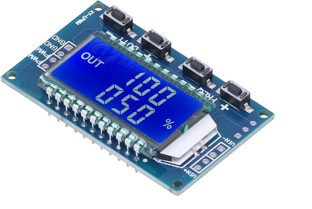 which works fine. It allows to control the speed of the motor, no issue. I can adjust the motor speed by setting the duty cycle to anything between 10% and 100% and it seems to be what I need.
Now the questions: Is it correct that in my situation the spindle interface of the 7i76 is just the wrong choice for my BLDC amplifier?
How do I make a PWM control for my spindle with the 7i76 (6i25)?
Greetings Timo
I tried to figure that out, but not really successful, so I spam the forum with the questions. (I have the feeling I should have found the information somewhere; maybe someone can point me in the right direction)
I have a 6i25 card with a 7i76 card connected to my PC. Some stepper motors are running and can be moved with keyboard, a basic configuration is running.
Now I got stuck, trying to hook up the old BLDC driver (labeled TONMAN Brushless DC driver) or the machine (which I have no documentation for) seems not to run with an analog input.
I tried to connect the Spindle interface somehow, but it does not want to run.
There is a pair of pins labeled +- (PWM / ANNA), but I think it is not really for analog input signal.
Hooking up a potentiometer (allowing to create a voltage between 0 and 5V) does nothing to a certain voltage. At approx. 2.6V it switches from "off" to "full speed".
I tried one of those PWM generators
Now the questions: Is it correct that in my situation the spindle interface of the 7i76 is just the wrong choice for my BLDC amplifier?
How do I make a PWM control for my spindle with the 7i76 (6i25)?
Greetings Timo
Time to create page: 1.546 seconds