- User Interfaces
- Other User Interfaces
- PathPilot
- Pathpilot on 5i25 + 7i76 config issues -> can't get past eStop lockout
Pathpilot on 5i25 + 7i76 config issues -> can't get past eStop lockout
- Dubmfg
-
 Topic Author
- Offline
- Senior Member
-

Less
More
- Posts: 49
- Thank you received: 1
12 Mar 2017 01:32 #89453
by Dubmfg
Replied by Dubmfg on topic Pathpilot on 5i25 + 7i76 config issues -> can't get past eStop lockout
I'm using show pins before and after applying vfield. I'm assuming watch works the same way, watch pins?
The screws are clamped right on pin1
The screws are clamped right on pin1
Please Log in or Create an account to join the conversation.
- tommylight
-

- Offline
- Moderator
-

Less
More
- Posts: 21750
- Thank you received: 7433
12 Mar 2017 11:07 #89461
by tommylight
Replied by tommylight on topic Pathpilot on 5i25 + 7i76 config issues -> can't get past eStop lockout
I do not recal how or what exactly, but pin 1 on the outer most connector on 7i77 is input 00 and it will not work in a certain mode. Use other inputs for testing. All other inputs work normaly. I do not know what mode i had it set but knowing me, i bet i had the mode with all options active.
Please Log in or Create an account to join the conversation.
- PCW
-

- Offline
- Moderator
-
Less
More
- Posts: 17991
- Thank you received: 5281
12 Mar 2017 15:03 #89469
by PCW
Replied by PCW on topic Pathpilot on 5i25 + 7i76 config issues -> can't get past eStop lockout
all inputs work as a digital inputs in all modes
The only difference is that in modes 1 and 2 you can also read the analog voltage on inputs 0,1,2,3
The only difference is that in modes 1 and 2 you can also read the analog voltage on inputs 0,1,2,3
The following user(s) said Thank You: tommylight
Please Log in or Create an account to join the conversation.
- tommylight
-
- Offline
- Moderator
-
Less
More
- Posts: 21750
- Thank you received: 7433
12 Mar 2017 19:14 #89483
by tommylight
Replied by tommylight on topic Pathpilot on 5i25 + 7i76 config issues -> can't get past eStop lockout
Oh that is why it did not show, i use a multimeter set to diode test connected between Vfield and inputs.
What resolution can they do, if i remeber correctly there should be 4 inputs that can do that.?
What resolution can they do, if i remeber correctly there should be 4 inputs that can do that.?
Please Log in or Create an account to join the conversation.
- PCW
-
- Offline
- Moderator
-
Less
More
- Posts: 17991
- Thank you received: 5281
12 Mar 2017 21:35 #89491
by PCW
Replied by PCW on topic Pathpilot on 5i25 + 7i76 config issues -> can't get past eStop lockout
4 inputs, 8 bit resolution
The following user(s) said Thank You: tommylight
Please Log in or Create an account to join the conversation.
- Dubmfg
-
Topic Author
- Offline
- Senior Member
-
Less
More
- Posts: 49
- Thank you received: 1
13 Mar 2017 04:24 - 13 Mar 2017 06:47 #89500
by Dubmfg
Replied by Dubmfg on topic Pathpilot on 5i25 + 7i76 config issues -> can't get past eStop lockout
So I've been able to set the eStop bit in the Hal to TRUE (1) and it has bypassed the estop issue, for now. I'm able to plug in and jog my X, Y, and Z axis' through pathpilot (small victory!)
I spent the majority of the day tidying up the wiring, and then got stumped again with my inductive limit switches. I changed out the GPIO pins they were calling in the HAL to hm2_5i25.0.7i76.0.0.input-01-not, as well as -02-not and -03-not for the Y and Z pins, respectively. I verified they were NO, passing 12V to the input pin until I place a metallic object on the sensor.
The only thing that I can think of now that I'm back home for the night and pondering is that the changes I made to the limit switch linking in the HAL could be it. The unmodified form looks like this:
net home-limit-x-raw <= hm2_5i25.0.gpio.014.in_not => debounce.0.0.in
net home-limit-y-raw <= hm2_5i25.0.gpio.015.in_not => debounce.0.1.in
net home-limit-z-raw <= hm2_5i25.0.gpio.016.in_not => debounce.0.2.in
The change I made looks like:
net home-limit-x-raw <= hm2_5i25.0.7i76.0.0.input-01-not => debounce.0.0.in
net home-limit-y-raw <= hm2_5i25.0.7i76.0.0.input-02-not => debounce.0.1.in
net home-limit-z-raw <= hm2_5i25.0.7i76.0.0.input-03-not => debounce.0.2.in
Could it be that the signal is now not making it back to the dedicated pins on the DB25 connection? I was working on the assumption that this was the correct place to make the pin address change.
all things aside,
When I bring pathpilot back up, I'm still unable to see my switches working. Is there some sort of external program I can run to monitor and live feedback the status of the 7i76 pins? From what I can understand the step/dir signals are natively carried across the DB25 cable, so at the very least its outputting to my drivers, but I still havent verified my 7i76 is functioning correctly besides being able to see its pin addresses using Halshow. What is the best way to for-sure test my IO? I'm banging my head against my desk here. Thanks!")
I spent the majority of the day tidying up the wiring, and then got stumped again with my inductive limit switches. I changed out the GPIO pins they were calling in the HAL to hm2_5i25.0.7i76.0.0.input-01-not, as well as -02-not and -03-not for the Y and Z pins, respectively. I verified they were NO, passing 12V to the input pin until I place a metallic object on the sensor.
The only thing that I can think of now that I'm back home for the night and pondering is that the changes I made to the limit switch linking in the HAL could be it. The unmodified form looks like this:
net home-limit-x-raw <= hm2_5i25.0.gpio.014.in_not => debounce.0.0.in
net home-limit-y-raw <= hm2_5i25.0.gpio.015.in_not => debounce.0.1.in
net home-limit-z-raw <= hm2_5i25.0.gpio.016.in_not => debounce.0.2.in
The change I made looks like:
net home-limit-x-raw <= hm2_5i25.0.7i76.0.0.input-01-not => debounce.0.0.in
net home-limit-y-raw <= hm2_5i25.0.7i76.0.0.input-02-not => debounce.0.1.in
net home-limit-z-raw <= hm2_5i25.0.7i76.0.0.input-03-not => debounce.0.2.in
Could it be that the signal is now not making it back to the dedicated pins on the DB25 connection? I was working on the assumption that this was the correct place to make the pin address change.
all things aside,
When I bring pathpilot back up, I'm still unable to see my switches working. Is there some sort of external program I can run to monitor and live feedback the status of the 7i76 pins? From what I can understand the step/dir signals are natively carried across the DB25 cable, so at the very least its outputting to my drivers, but I still havent verified my 7i76 is functioning correctly besides being able to see its pin addresses using Halshow. What is the best way to for-sure test my IO? I'm banging my head against my desk here. Thanks!
Last edit: 13 Mar 2017 06:47 by Dubmfg.
Please Log in or Create an account to join the conversation.
- rodw
-

- Offline
- Platinum Member
-

Less
More
- Posts: 12041
- Thank you received: 4109
13 Mar 2017 09:22 - 13 Mar 2017 09:25 #89505
by rodw
Replied by rodw on topic Pathpilot on 5i25 + 7i76 config issues -> can't get past eStop lockout
Are your sensors PNP or NPN type?
PNP sensors are best for Mesa hardware. If you have NPN sensors which I suspect you have, you need to add some pullup resistors between the signal wire and the positive voltage. PCW told me to use 2.2 k ohms, 1 W resistors and that worked a treat ( I think I might have used 2.0k Ohms)
EDIT: I did not use debounce and never had any problems. I don't think bounce is an issue with prox sensors.
Last edit: 13 Mar 2017 09:25 by rodw.
Please Log in or Create an account to join the conversation.
- smgvbest
-

- Offline
- Elite Member
-

Less
More
- Posts: 311
- Thank you received: 51
13 Mar 2017 13:11 #89514
by smgvbest
Replied by smgvbest on topic Pathpilot on 5i25 + 7i76 config issues -> can't get past eStop lockout
Hi, sorry to be jumping in here
So first thing as I did not see it asked
on your 7i76 are both LEDs on?
you should have 2. one near the DB25 and 1 near the field power connector (TB1)
what are your W1/W2 jumpers set to?
next, what does a dmesg | grep 7i76 show?
if the above is not true you should get nothing returned for this command.
Next. are you using P3 to plug into the 7i76? this is the DB2 on the card itself, not the 26pin header for a DB2 connector.
if not that could be a reason for your problem as the address would change. the dmesg will show this so please paste the output into the chat?
sorry for the basics questions but let make sure the basic setup is working before troubling HAL problems.
so lets see what happens there and if the basics are indeed correct.
for the HAL problems (which maybe you have none and the above is the problem)
it would be very helpful to follow this thread forum.linuxcnc.org/pathpilot/32055-halshow
and get ADMIN HALSHOW working which will provide a gui so you can what pins in real time
from what I see your doing ADMIN HALCMD SHOW PINS which is a pain for troubleshooting.
side note on pull up resistors, you don't need 1W resistors 12V@2K is only 6mA so a 1/8W is all you need. 1/4 is cheaper and more abundant so 2K@1/4W would due well but if using a Proximity switch (which I am also) they draw around 20mA or less so for 12V@20mA you need ~ 600Ohm resistors and at 240mW a 1/8W again would work but 1/4W tend to be more available and cheaper.
Please Log in or Create an account to join the conversation.
- smgvbest
-
- Offline
- Elite Member
-
Less
More
- Posts: 311
- Thank you received: 51
13 Mar 2017 13:29 #89517
by smgvbest
Replied by smgvbest on topic Pathpilot on 5i25 + 7i76 config issues -> can't get past eStop lockout
just saw you do have W1/W2 to the left so you should only have field power connected to the board.
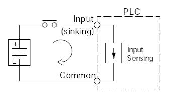
one thing it could also be since inputs are sinking that you might have them incorrectly setup
for a sinking input you must supply the positive voltage
so your switch (best way to troubleshoot is with a switch) should have +12V on one side and the other goes to the input pin.
if you have GND on one side of the pin and the other side to the input you won't see any change when you toggle the switch.
here's a nice pic of sinking inputs
Please Log in or Create an account to join the conversation.
- Dubmfg
-
Topic Author
- Offline
- Senior Member
-
Less
More
- Posts: 49
- Thank you received: 1
13 Mar 2017 14:45 - 13 Mar 2017 14:59 #89522
by Dubmfg
Replied by Dubmfg on topic Pathpilot on 5i25 + 7i76 config issues -> can't get past eStop lockout
Thanks for the reply! I don't have a resistor in the signal in, I would have assumed sensing 12v+ would be enough to work, without a resistor. I've currently got 12V+ directly connected from the power connector to pins 0,1,2,and 3 on TB6.
I do see the pins on 7i76 on Halshow pin.
I'll give the resistors a try this morning. Is the same required for say, an e stop? Everything needs a 2.2k ohm resistor?
I've tried using both the 26pin header on the 5i25 to the DB25 on the 7i76 as well as using DB25->DB25 connecting cable. Currently using the DB25-DB25
Last edit: 13 Mar 2017 14:59 by Dubmfg.
Please Log in or Create an account to join the conversation.
- User Interfaces
- Other User Interfaces
- PathPilot
- Pathpilot on 5i25 + 7i76 config issues -> can't get past eStop lockout
Time to create page: 0.124 seconds