Lets Talk Wiring And EMI
- AgentWD40
-
 Topic Author
- Offline
- Platinum Member
-

Less
More
- Posts: 339
- Thank you received: 96
04 Jun 2019 13:44 #135833
by AgentWD40
Lets Talk Wiring And EMI was created by AgentWD40
I'm building a simple low budget plasma table. I know plasma is on a whole new level when it comes to emi. At the moment I'm focusing on planning out my control panel. I've been looking around trying to find examples of what everyone else has done and reading what I can on minimizing EMI.
I've read the hypertherm article on grounding. I've read bits here and there on a 100 different forum posts around the web. I thought I had a pretty good grasp at how I would approach my build. But then I found a youtube channel by corvetteguy50.. I can't tell if this guy really knows what he's talking about or if he's trying to scare the sh*t out of everyone into just buying his really expensive custom products.
For example double shielded cable is "mandatory". All connections must be soldered, no crimps, it's "mandatory". Leads from bob to drivers, shielded, "mandatory". Leads from bob to chassis mount cable connector shielded, "mandatory". Absolutely no doubling up connectors on a screw post. Obviously when you have shielded cable you have to drain one end, so right there is at least 15 individual shields to be grounded and at least 10 more posts on the grounding terminal block. My little enclosure is going to be filling up quickly with terminal blocks.
What I'm getting at is, in your experience at what lengths did you have to go to protect your control box from EMI?
Follow up question: Where would you all prefer to mount your THCAD? In your control panel or in it's own enclosure next to the plasma machine? Doesn't really matter?
Please Log in or Create an account to join the conversation.
- tecno
-

- Offline
- Platinum Member
-
Less
More
- Posts: 1850
- Thank you received: 127
04 Jun 2019 14:13 #135836
by tecno
Replied by tecno on topic Lets Talk Wiring And EMI
Error 404 ") To many words *mandatory*
To many words *mandatory*
To many words *mandatory* Please Log in or Create an account to join the conversation.
- PCW
-

- Offline
- Moderator
-

Less
More
- Posts: 17976
- Thank you received: 5275
04 Jun 2019 14:18 - 04 Jun 2019 14:30 #135837
by PCW
Replied by PCW on topic Lets Talk Wiring And EMI
If you have a CNC compatible plasma source with a voltage divider, I would mount the
THCAD inside your electronics enclosure with all the other motion hardware.
If you have a manual plasma source and you are reading raw plasma voltage, I would
mount the THCAD as close to the plasma source as possible (even inside the plasma
source case if it fits.) In this case, make sure that all low side THCAD connections are
fully isolated from the plasma source. If you use a shielded box for the THCAD, the
shield should connect to your electronic enclosure ground, not the plasma source ground.
BTW i think corvetteguy50 is using "voodoo" EMI prevention techniques, most of which are just silly.
One thing I have learned about EMI is that at the frequencies of an arc start (Picosecond risetimes),
all ground points are just taps along an inductor and its much much easier to increase the impedance
of critical paths with resistance or ferrite beads so transient currents do no flow along undesired paths than
brute force attempts to lower ground impedance in the desired path
Last edit: 04 Jun 2019 14:30 by PCW.
The following user(s) said Thank You: Clive S, AgentWD40
Please Log in or Create an account to join the conversation.
- islander261
- Offline
- Platinum Member
-
Less
More
- Posts: 757
- Thank you received: 216
04 Jun 2019 15:17 - 04 Jun 2019 15:22 #135838
by islander261
Replied by islander261 on topic Lets Talk Wiring And EMI
Ok
The first thing is to determine what type of arc starting your plasma uses. If it is a HF/HV start then pay close attention to the HT documents. If it is a blowback start, modern HT, TD and some Everlast air plasma then things are easier. On My system which has NEVER had any EMI problems I did this:
1. Star ground to table frame for work piece lead and everything that connects to it, slats, work piece clamp, ohmic sensing. If you have a HF/HV start plasma the ground rod also connects here.
2. Single shielded (screened) cables for all control connections to table parts. Shields terminated and connected to chassis (safety) ground only at control enclosure end.
3. Arc voltage divider mounted inside plasma power supply. My voltage divider has HF filtering built in to catch any HF/HV starting pulses but is most likely an over complicated version of what PCW suggested. I have a blowback start plasma power supply.
4. THCad card mounted in shielded box ( die cast alloy) next to plasma power supply. Local 5V power supply for THCad supplied with field power from control enclosure. Shielded CAT 5 cable between THCad box and control enclosure.
5. The safety ground for my buildings power supply is above the minimum code requirement for a shop. Ground rods at service entrance (meter box and building disconnect breaker) out by street. 4 AWG ground connection between service entrance and shop. Two more ground rods at shop. Rebar in concrete welded and connected to safety ground rods at shop. No safety ground connections using the conduit as the conductor. Conduit is all connected to safety ground. Neutral conductor is only connected (bonded) to safety ground at service entrance as required by code here. If you don't know what some of this means get a licensed electrician to help you out.
John
Last edit: 04 Jun 2019 15:22 by islander261.
The following user(s) said Thank You: AgentWD40
Please Log in or Create an account to join the conversation.
- AgentWD40
-
Topic Author
- Offline
- Platinum Member
-
Less
More
- Posts: 339
- Thank you received: 96
04 Jun 2019 17:49 #135849
by AgentWD40
Replied by AgentWD40 on topic Lets Talk Wiring And EMI
Okay, so I've got the green light to use crimp terminals and don't need to solder every damn connection then?
Is it necessary to use shielded cable for all the signal wires within the grounded metal enclosure? I figure I can 'upgrade' to that later if I experience problems.
The plasma machine will be a HT 45xp. So I'll put the thcad in the main control box.
Is it necessary to use shielded cable for all the signal wires within the grounded metal enclosure? I figure I can 'upgrade' to that later if I experience problems.
The plasma machine will be a HT 45xp. So I'll put the thcad in the main control box.
Please Log in or Create an account to join the conversation.
- islander261
- Offline
- Platinum Member
-
Less
More
- Posts: 757
- Thank you received: 216
04 Jun 2019 18:14 #135851
by islander261
Replied by islander261 on topic Lets Talk Wiring And EMI
AgentWD40
You only need shielded wiring for external wiring.
My system uses crimp terminals and furrels where ever possible.
You should have no EMI problems from your 45XP.
John
You only need shielded wiring for external wiring.
My system uses crimp terminals and furrels where ever possible.
You should have no EMI problems from your 45XP.
John
Please Log in or Create an account to join the conversation.
- JTknives
-

- Offline
- Elite Member
-

Less
More
- Posts: 243
- Thank you received: 32
04 Jun 2019 19:37 #135853
by JTknives
Replied by JTknives on topic Lets Talk Wiring And EMI
So how do you know if you have EMI problems. I did not use any shielded cables in my build and everything seams to work peachy. I’m running a 30XP so no Hz start. Also my THCAD10 is in my main control cabinet.
Please Log in or Create an account to join the conversation.
- mozmck
- Offline
- Administrator
-

Less
More
- Posts: 49
- Thank you received: 59
04 Jun 2019 20:04 #135855
by mozmck
Replied by mozmck on topic Lets Talk Wiring And EMI
If you have EMI problems things won't work correctly. You might fire the torch and the computer will reboot in a more obvious example, but you can have any number of other odd symptoms. They will pretty much all happen only when the torch is cutting - often when it is first fired.
Shielding is not needed for every external wire - I have never seen a problem with unshielded wires from between drives and stepper motors. Those are high current, and it would take a lot of noise to cause any problems there. Shielding on those wires might be good in cases to reduce noise created by the high-power step currents from radiating out. I'm not sure if you might be better off with ferrite beads though - PCW would know a lot better than I about that.
Now for an HF start high-power machine, you do have to be more careful and aggressive with grounding/shielding/ferrites etc. I have little experience with that myself though.
The following user(s) said Thank You: AgentWD40
Please Log in or Create an account to join the conversation.
- rodw
-

- Offline
- Platinum Member
-
Less
More
- Posts: 12007
- Thank you received: 4089
04 Jun 2019 20:51 #135857
by rodw
Replied by rodw on topic Lets Talk Wiring And EMI
I think a lot about EMI/RFI has been written for HF start machines. Running a 24 volt logic system as we do with Mesa cards is a big step up from the lower voltages of the Mach3 community
Designing for noise starts with good control box layout
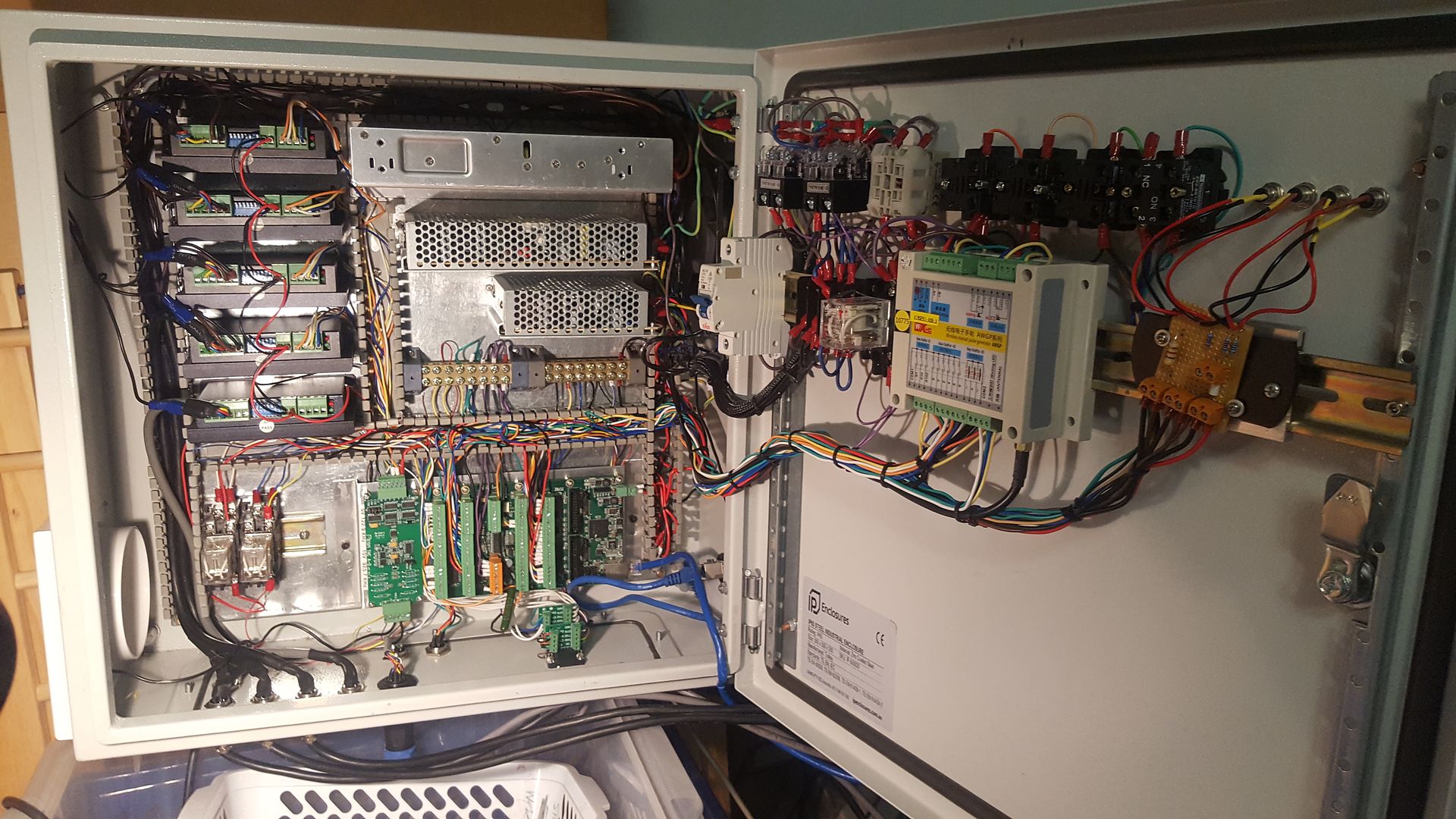
Mains power segregated from the rest on the top right corner (and top left of door)
48 Volt power to steppers routed around the top to stepper drivers at the top left
Signal wires routed seperately above the 7i76e
External wiring exiting from the bottom with steppers fairly isolated from the rest.
As far as external wiring goes and ignoring plasma for a moment, the motor wiring is the most significant source of noise. Its expensive but purchase shielded wire with thick enough cores to carry the required current. We elected to use 5 pin connectors on the case for stepper motor cables and attached the ground/shield to one of them. Inside the case, we used more of the same shielded cable to run to the controllers, and attached a spade connector to the shield right at the controller and folded this back and secured with shrinkwrap. We connected these to one of the copper earthing points provided on the industrial case we used. Subsequently, I upgraded the IEC connector on the mains inlet to a IEC RFI filtered one. They only cost a few dollars so its cheap insurance. Do not connect the shield at the motor end.
All wiring to the gantry is via 9 core shielded cable and I have breakout boards and terminal strips to distribute these signals. I used DB9 connectors and in the control box, I used DB9 connectors with breakout boards and terminals on them which made it easy to wire up.
Then I upgraded the wiring to include a star ground attached to the table and followed the Hypertherm document. I think this is a good Idea. I resisted for a while but if nothing else it provides a clear ground path around the linear rails back to the table frame. It would have been pretty easy if it was done when I first wired everything up.
Currently, I have not attached the star ground to any external earth so I guess it depends on the mains earth wire. When the machine was at home it was very close to the main building earth so I earthed the table and the plasma cutter back to it by seperate wires. This definitely reduced noise when I prodded with an Oscilloscope.
I debated for a long time whether I should mount the control box to the table or not as a seperate controlbox would also reduce the impact of noise but in the end I did and have not had any dramas.
I'm sure you will be fine with your machine. If you get Spurious random errors, its likely noise.
So for plasma, I think what I've outlined is all you need to do for a blow back style torch (eg, Hypertherm, Thermal Dynamcs, Everlast).
If you have a HF start, I think you need to add the ground rod and also be aware of the potential for noise spuriously triggeirng the probe signal from the Ohmic sensing wire. With the Islander/Plasmac probe design, this should not be an issue as it is physically disconnected unless probing. With other designs, if you have spurious Ohmic triggers, my HF consultant reckons the way to go is to fit a Feed through power line filter where it enters the control box.
Designing for noise starts with good control box layout
Mains power segregated from the rest on the top right corner (and top left of door)
48 Volt power to steppers routed around the top to stepper drivers at the top left
Signal wires routed seperately above the 7i76e
External wiring exiting from the bottom with steppers fairly isolated from the rest.
As far as external wiring goes and ignoring plasma for a moment, the motor wiring is the most significant source of noise. Its expensive but purchase shielded wire with thick enough cores to carry the required current. We elected to use 5 pin connectors on the case for stepper motor cables and attached the ground/shield to one of them. Inside the case, we used more of the same shielded cable to run to the controllers, and attached a spade connector to the shield right at the controller and folded this back and secured with shrinkwrap. We connected these to one of the copper earthing points provided on the industrial case we used. Subsequently, I upgraded the IEC connector on the mains inlet to a IEC RFI filtered one. They only cost a few dollars so its cheap insurance. Do not connect the shield at the motor end.
All wiring to the gantry is via 9 core shielded cable and I have breakout boards and terminal strips to distribute these signals. I used DB9 connectors and in the control box, I used DB9 connectors with breakout boards and terminals on them which made it easy to wire up.
Then I upgraded the wiring to include a star ground attached to the table and followed the Hypertherm document. I think this is a good Idea. I resisted for a while but if nothing else it provides a clear ground path around the linear rails back to the table frame. It would have been pretty easy if it was done when I first wired everything up.
Currently, I have not attached the star ground to any external earth so I guess it depends on the mains earth wire. When the machine was at home it was very close to the main building earth so I earthed the table and the plasma cutter back to it by seperate wires. This definitely reduced noise when I prodded with an Oscilloscope.
I debated for a long time whether I should mount the control box to the table or not as a seperate controlbox would also reduce the impact of noise but in the end I did and have not had any dramas.
So how do you know if you have EMI problems. I did not use any shielded cables in my build and everything seams to work peachy. I’m running a 30XP so no Hz start. Also my THCAD10 is in my main control cabinet.
I'm sure you will be fine with your machine. If you get Spurious random errors, its likely noise.
So for plasma, I think what I've outlined is all you need to do for a blow back style torch (eg, Hypertherm, Thermal Dynamcs, Everlast).
If you have a HF start, I think you need to add the ground rod and also be aware of the potential for noise spuriously triggeirng the probe signal from the Ohmic sensing wire. With the Islander/Plasmac probe design, this should not be an issue as it is physically disconnected unless probing. With other designs, if you have spurious Ohmic triggers, my HF consultant reckons the way to go is to fit a Feed through power line filter where it enters the control box.
Please Log in or Create an account to join the conversation.
- rodw
-
- Offline
- Platinum Member
-
Less
More
- Posts: 12007
- Thank you received: 4089
04 Jun 2019 21:16 #135862
by rodw
Yes, the risk is noise affecting other electronics. Plus its just another antenna out there in plasma world. to conduct the nasties back into the control box. Thats why I was advised to continue the shield right through into the control box right to the stepper controller. I don't think many people go that far.
A few hours extra work building your machine at the beginning can save hours of fruitless trobleshooting down the track.
Replied by rodw on topic Lets Talk Wiring And EMI
Shielding is not needed for every external wire - I have never seen a problem with unshielded wires from between drives and stepper motors. Those are high current, and it would take a lot of noise to cause any problems there. Shielding on those wires might be good in cases to reduce noise created by the high-power step currents from radiating out. I'm not sure if you might be better off with ferrite beads though - PCW would know a lot better than I about that.
Yes, the risk is noise affecting other electronics. Plus its just another antenna out there in plasma world. to conduct the nasties back into the control box. Thats why I was advised to continue the shield right through into the control box right to the stepper controller. I don't think many people go that far.
A few hours extra work building your machine at the beginning can save hours of fruitless trobleshooting down the track.
Please Log in or Create an account to join the conversation.
Moderators: snowgoer540
Time to create page: 0.403 seconds