
Search Results (Searched for: )
- tuxcnc
02 Oct 2026 08:49
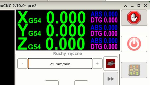
Replied by tuxcnc on topic Re-designing the Gmoccapy DRO
- tuxcnc
02 Oct 2026 07:52
Replied by tuxcnc on topic Would you use a feed rate for rotary axes in mm/min (surface speed)?
First of all, GIGO, i.e. processing incorrect data, gives incorrect results.
You can also say that if you ask the wrong question, all the answers will be wrong...
Questions like who would like to do it and whether to do it are the wrong questions, especially when asking a small and non-representative group of a few active users of this forum.
The real question is: HOW NOT TO DO THIS?
And here we know the right answer - NOT like in Mach3.
Mach3 is commercial software, which means that nothing is done to make it work good, but to make the users like it, because the company's income depends on the users' satisfaction.
It works differently in free software - if someone has the time and inclination, they add a new utility, and if someone doesn't like it, they don't use it.
The only problem here is not to break anything and not to let a program with a twenty-year history suddenly start working in a way that is unpredictable for the user.
But let's get back to Mach3.
I don't have the time or inclination to look for better examples, but what I quickly found is completely enough. Here is one of the many screens for changing Mach3 settings:
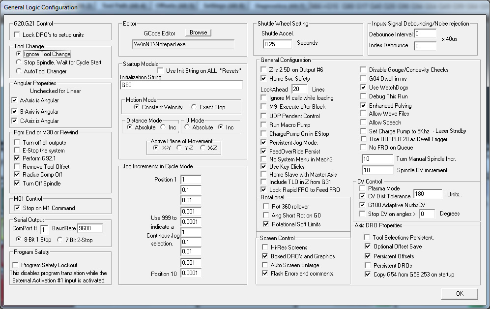
Notice the "G04 dwell ms" entry in the upper right corner.
The way it works is that depending on whether this item is selected or deselected, the G04 code is interpreted in a different way. There is no need to explain the difference between 3 seconds and 3 milliseconds, and the g-code author may have no idea how his code will be executed.
Let's ignore the sobbing of the operator when his disk goes bad and he has to recreate all the windows and buttons, because that would be offtopic.
The utility we are talking about here is implemented in Mach3. AI writes about it this way:
Basically everything is true.
Let's not do the same in LinuxCNC.
The definition of g-code is that it is a description of the tool path and let's stick to it.
The same g-code should be executed in the same way on different machines, and not on each machine differently because the operator changed something in settings...
You can also say that if you ask the wrong question, all the answers will be wrong...
Questions like who would like to do it and whether to do it are the wrong questions, especially when asking a small and non-representative group of a few active users of this forum.
The real question is: HOW NOT TO DO THIS?
And here we know the right answer - NOT like in Mach3.
Mach3 is commercial software, which means that nothing is done to make it work good, but to make the users like it, because the company's income depends on the users' satisfaction.
It works differently in free software - if someone has the time and inclination, they add a new utility, and if someone doesn't like it, they don't use it.
The only problem here is not to break anything and not to let a program with a twenty-year history suddenly start working in a way that is unpredictable for the user.
But let's get back to Mach3.
I don't have the time or inclination to look for better examples, but what I quickly found is completely enough. Here is one of the many screens for changing Mach3 settings:
Notice the "G04 dwell ms" entry in the upper right corner.
The way it works is that depending on whether this item is selected or deselected, the G04 code is interpreted in a different way. There is no need to explain the difference between 3 seconds and 3 milliseconds, and the g-code author may have no idea how his code will be executed.
Let's ignore the sobbing of the operator when his disk goes bad and he has to recreate all the windows and buttons, because that would be offtopic.
The utility we are talking about here is implemented in Mach3. AI writes about it this way:
Code:
To set up the rotation radius for your rotary (A-axis) in Mach3, enter the distance from the center of rotation to your material surface in the Settings tab.
Step-by-Step Configuration
• Enable Toolpath Settings: Go to Config > Toolpath in the top menu. Check the options for A-Rotations Enabled and use radius/feedrate correction if available. Click Save Settings.
• Set Angular Properties: Go to Config > General Config, look for Angular Properties on the left side, and check A Axis is Angular. Click OK and restart Mach3.
• Enter the Rotation Radius: Navigate to the Settings tab on the main screen. Look for the Rotation Radius (or A-radius/diameter DRO) field near the top right.
• Input Your Measurement: Type the exact radius (or half-diameter) of your current workpiece material into the A-axis box and press ENTER. For example, if your stock is 2 inches across, enter 1.0. (If your Z-zero is set directly at the center of rotation, enter a very small nominal value like 0.001).
• Verify the Setup: Return to the Program Run tab. Check that the Radius Correct LED indicator next to the A-axis display turns lit/yellow, which confirms Mach3 is properly using the radius to calculate coordinated feedrates and graphics. Remember to update this value whenever you change stock sizes.
Let's not do the same in LinuxCNC.
The definition of g-code is that it is a description of the tool path and let's stick to it.
The same g-code should be executed in the same way on different machines, and not on each machine differently because the operator changed something in settings...
- grandixximo
-

02 Oct 2026 07:36
Replied by grandixximo on topic Re-designing the Gmoccapy DRO
I think the A 0.000 should align right with the numbers above Z-10,000, where the last two zeros are on top of each other, maybe the dtgs could get a slightly less bright red to distinguish them more visibly.
Not sure why A and B needs the smaller text size, but looks ok.
You are removing information though, the Abs might deserve a switch, maybe on click/tap? maybe with some kind of hint, clicking on dtg changes it to abs?
Food for thoughts, not implementation requests
Not sure why A and B needs the smaller text size, but looks ok.
You are removing information though, the Abs might deserve a switch, maybe on click/tap? maybe with some kind of hint, clicking on dtg changes it to abs?
Food for thoughts, not implementation requests
- HansU
02 Oct 2026 07:02
Re-designing the Gmoccapy DRO was created by HansU
Currently there is much (unused) space between the axis letter and the value:

I thought the space could be used more effectively, so I moved one of the tiny sized values to the right and display the labels only at the top.
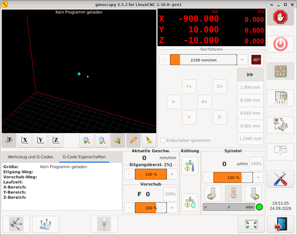
And I would display the current coordinate system (G5x) fixed at this position and only toggle the display of the right part.
For more than 4 axes I would only display the main value:
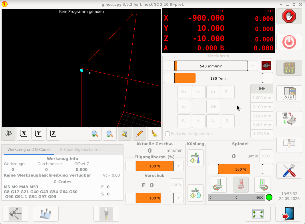
What do you think about that new design?
I thought the space could be used more effectively, so I moved one of the tiny sized values to the right and display the labels only at the top.
And I would display the current coordinate system (G5x) fixed at this position and only toggle the display of the right part.
For more than 4 axes I would only display the main value:
What do you think about that new design?
- grandixximo
-
02 Oct 2026 03:40 - 02 Oct 2026 03:42
Replied by grandixximo on topic Would you use a feed rate for rotary axes in mm/min (surface speed)?
Yes, I will try to make the least assumptions as possible, you could be working from Z0 center, or not, you could be working on a lathe or a mill, the spindle could be spinning or the table, you might want the feed to match the tip the side or half way trough the shaft of a tool, I think we need some flexibility, but I'd also compare with what other controllers do, and what a CAM or someone hand writing a gcode would expect...
- spumco
02 Oct 2026 03:34
Replied by spumco on topic Would you use a feed rate for rotary axes in mm/min (surface speed)?
Just thinking about this a bit...
I wonder if a new non-modal gcode could be created that didn't use any INI settings, and simple calculated the appropriate angular feedrate based on the Z0 being at the center of rotation.
In my CAM I have to set A-axis CoR to Z0 for it to work properly, even for simple indexing work. I wonder if other users are 'used to' programming a rotary axis - at least a 4th axis - with CoR as Z0?
I also wonder if this is going to be more complicated... what if the tool is not just cutting on the rotational axis centerline? Will the new Gcode/Mcode change (or work with) the trajectory planner to determine the 'real' radius based on rotational axis offset, plus tool diameter?
Sounds like it might get interesting.
I wonder if a new non-modal gcode could be created that didn't use any INI settings, and simple calculated the appropriate angular feedrate based on the Z0 being at the center of rotation.
In my CAM I have to set A-axis CoR to Z0 for it to work properly, even for simple indexing work. I wonder if other users are 'used to' programming a rotary axis - at least a 4th axis - with CoR as Z0?
I also wonder if this is going to be more complicated... what if the tool is not just cutting on the rotational axis centerline? Will the new Gcode/Mcode change (or work with) the trajectory planner to determine the 'real' radius based on rotational axis offset, plus tool diameter?
Sounds like it might get interesting.
- grandixximo
-
02 Oct 2026 03:13 - 02 Oct 2026 03:17
Replied by grandixximo on topic Would you use a feed rate for rotary axes in mm/min (surface speed)?
Problem is if "stupidly slow" was a behavior anyone relied upon, or already based something on, tuxcnc has a point there, there could be subs out there that fixed this issue in gcode, and we might not what to change their behavior with a new default, is just something we have to account for, we have enough users where these seemingly rare occurrences might bite quite a few ppl...
A new INI to force a sensible default, and leaving old configs unchanged seems the right balance.
---
And replying "G93 works for me" is totally fine, this was more of a census to see how many users actually would use the feature, and who already had it covered, one doesn't detract from the other, but give me a rough idea of who looked at it, and who I can ping for testing once it's built
A new INI to force a sensible default, and leaving old configs unchanged seems the right balance.
---
And replying "G93 works for me" is totally fine, this was more of a census to see how many users actually would use the feature, and who already had it covered, one doesn't detract from the other, but give me a rough idea of who looked at it, and who I can ping for testing once it's built
- djdelorie
01 Oct 2026 23:31
Also, my third option gave the machine the math it needed to calculate the correct speeds.
Replied by djdelorie on topic Would you use a feed rate for rotary axes in mm/min (surface speed)?
Sure, but as I noted, sometimes I forget to use G93 and happen to include an A move in something innocuous, and it would be nice if the resulting motion was at least within an order of magnitude of correct instead of the default of stupidly slow.These are mathematical heresies
Also, my third option gave the machine the math it needed to calculate the correct speeds.
- dbtayl
01 Oct 2026 23:29 - 02 Oct 2026 22:51
Replied by dbtayl on topic Perpetual License CAM
So far a mixed bag for me. For context, I normally use FreeCAD's CAM, which is honestly really good most of the time... except for occasionally breaking in seemingly incredibly dumb ways (ie, simple contour operations have gotten broken multiple times). That's been frustrating enough I was willing to try throwing some money at the problem- looking for a stop-gap "works" solution until FreeCAD stabilizes enough to stop driving me up the wall. No matter how good a standalone CAM package gets, not being integrated with your CAD is a hindrance.
Most of the stuff I do is multiple tools, generally "2.5D" (ie, very little surfacing), but operations on multiple sides and undercuts are common. Normally I'll use adaptive to rough the inside and outside- sometimes different areas w/ different stepdowns to optimize MRR- then add some contours/finishing passes to clean up edges/corners. Drill, undercut, chamfer/deburr, then cut off and flip for the other side.
The below is a "review" of version 1.0.7. Full disclosure I've only messed with it for a couple hours, so I may be wrong about some of these things! It's possible I just haven't figured out how to do stuff yet.
My current take is that it's a nice teaser/tech demo, but doesn't have nearly enough control to make parts in practice. Everything I listed in the "bad" section below is pretty much a breaking issue for me (YMMV!). That said, I really don't want to be too negative here- the core (actual toolpath generation) seems to work really well! It "just"- fully recognizing that may be a huge task- needs maybe 2-3x as many options for controlling the details of those paths to make it actually useful. (again, for me- YMMV)
If it looks like progress is being made a couple weeks from now I'll probably think it's worth gambling the $200 that it'll get usable for me someday, otherwise I'll be considering the 30-day refund policy.
The good:
The odd:
The bad (a lot of these boil down to "not enough control"):
I haven't tried a lot of stuff (surfacing, tapping, drilling, actually posting g-code, ...).I tried the automatic feature recognition a bit, and it was hit-and-miss. (Issues with the AFR do not appear to be with AFR itself, but rather things I selected after that showing up in the AFR list. So of course me selecting nonsense looked like bad AFR. Still a problem, just a very different one, and not AFR itself) I have not tried the tool library functionality enough to know how good a job it does of remembering speeds/feeds for different materials/operations/etc.
I somehow thought there was a simulator included, but on further inspection it looks like I made that up based on the collision detection feature, so that's on me. Can always use Camotics, but bouncing between 3 programs while making a model is more obnoxious than just 2.
Most of the stuff I do is multiple tools, generally "2.5D" (ie, very little surfacing), but operations on multiple sides and undercuts are common. Normally I'll use adaptive to rough the inside and outside- sometimes different areas w/ different stepdowns to optimize MRR- then add some contours/finishing passes to clean up edges/corners. Drill, undercut, chamfer/deburr, then cut off and flip for the other side.
The below is a "review" of version 1.0.7. Full disclosure I've only messed with it for a couple hours, so I may be wrong about some of these things! It's possible I just haven't figured out how to do stuff yet.
My current take is that it's a nice teaser/tech demo, but doesn't have nearly enough control to make parts in practice. Everything I listed in the "bad" section below is pretty much a breaking issue for me (YMMV!). That said, I really don't want to be too negative here- the core (actual toolpath generation) seems to work really well! It "just"- fully recognizing that may be a huge task- needs maybe 2-3x as many options for controlling the details of those paths to make it actually useful. (again, for me- YMMV)
If it looks like progress is being made a couple weeks from now I'll probably think it's worth gambling the $200 that it'll get usable for me someday, otherwise I'll be considering the 30-day refund policy.
The good:
- Runs on Linux, perpetual license- want to encourage that!
- Speed seems good, both in general use and generating toolpaths (though have only tried small models)- again, very nice in a world full of (eg) node.js burn-your-cpu-to-render-1-fps nonsense.
- Not mysteriously 10 GB for reasons I can't comprehend!
- Adaptive toolpaths!!!
- Actually runs offline- Wireshark confirms that (only ran it for a few minutes, so hardly a conclusive test), manual is offline as well
- Supported 3Dconnexion mouse out of the box
The odd:
- Defaults: G43 disabled, 3D mouse Z inverted
- Output includes "2026-09-30T20:03:01-0500 INFO frontend.licensing.gate: [LICENCE] active, licence_id=xxxxxxxx... updates until 2029-09-27", maybe just a placeholder ETA for when this major version will be done
- Payment tripped fraud alert, made 3-4 authorizations, though only one of them turned into a real charge
- UI/workflow is definitely different from FreeCAD and Fusion 360. It seems buggy to me (creating/deleting operations, notably), but I'm trying to withhold judgement until I've used it more.
The bad (a lot of these boil down to "not enough control"):
- Adaptive ONLY appears to machine the inside of your part- if you want to rough the outside, too bad, I guess?
- Adaptive has no option to force specific depths- it has a stepdown setting, but will always do Z plane detection and cut any depth it finds one. Really breaks the high-DOC-low-WOC idea of adaptive in practice- especially since it cuts top-down, instead of cutting the bulk out from the bottom, then rest-machining the next layer up, and so on.
- Chamfer operation is real rough. Sometimes it works when you select a top or bottom face (to chamfer all edges of said face), sometimes it doesn't. Manually selecting edges kinda works, but the hit box for edges is tiny, and the closed loop detection seems to only sometimes work. You can't seem to de-select edges by clicking on them in the model, you need to find them in the list. Some edges it seems to entirely refuse to recognize.
- No option I can find for ramping into pockets- helix or plunge only. Problematic if you have a long, narrow pocket that you want to ease into, but no space for a helix. Literally the only time I accept a plunge entry is drilling.
- Lead-in/-out options are limited- you can pick a lead-in radius on some operations, but not others, and you can't add a slight overlap between the lead-in and -out points on closed contours
Collision detection seems over-sold- eg, the chamfer operation will happily crash into a wall where the edge you're chamfering meets another face.See below- I misinterpreted the website, my fault.- I'm also not seeing a way to control where an operation starts or to add offsets to start/stop points to manually work around that. Looks like it only does collision detection for 3D operations
I haven't tried a lot of stuff (surfacing, tapping, drilling, actually posting g-code, ...).
I somehow thought there was a simulator included, but on further inspection it looks like I made that up based on the collision detection feature, so that's on me. Can always use Camotics, but bouncing between 3 programs while making a model is more obnoxious than just 2.
- PCW
01 Oct 2026 21:31 - 01 Oct 2026 21:49
Replied by PCW on topic Servo Driver Plasma Retrofit
This can likely be fixed in a couple of different ways:
1. Adjust the input zero on the analog servo drive till the static following
error is near zero.
2. Set the PID bias pin to a small value (say somewhere between -.020 to +.020),
again, till the static following error is near zero
(#1 or #2 have equivalent effects, minimizing any small offsets)
3. Add some integral (I) term to the PID loop
This will zero any static error.
Best option is probably to do 1 or 2 first to eliminate any offset errors
then do 3 (you cannot set 1 or 2 unless the I term is 0)
1. Adjust the input zero on the analog servo drive till the static following
error is near zero.
2. Set the PID bias pin to a small value (say somewhere between -.020 to +.020),
again, till the static following error is near zero
(#1 or #2 have equivalent effects, minimizing any small offsets)
3. Add some integral (I) term to the PID loop
This will zero any static error.
Best option is probably to do 1 or 2 first to eliminate any offset errors
then do 3 (you cannot set 1 or 2 unless the I term is 0)
- spumco
01 Oct 2026 21:30
"G93 is fine for me" means
Inverse-time feedrate generated by CAM is sufficient for my needs.
The OP indicated a simple response would be sufficient. I gave one of the requested responses.
If your provocative post was not directed at me, disregard.
And, as usual, thank you grandixximo for all the work on LCNC.
Replied by spumco on topic Would you use a feed rate for rotary axes in mm/min (surface speed)?
"G93 is fine for me" means nothing.
"G93 is fine for me" means
Inverse-time feedrate generated by CAM is sufficient for my needs.
The OP indicated a simple response would be sufficient. I gave one of the requested responses.
If your provocative post was not directed at me, disregard.
And, as usual, thank you grandixximo for all the work on LCNC.
- tommylight
-

01 Oct 2026 21:19
Replied by tommylight on topic Servo Driver Plasma Retrofit
15in/s2 is 380mm/s2, from pictures the gantry seems really heavy, so you might want to tr 10 or eve 7in/s2.
This does not limit the cutting speed, it just limits the speed on corners, so you might have to also adjust the VAD to 80 or 90%, depending on the amount of dross remaining in the corners.
This does not limit the cutting speed, it just limits the speed on corners, so you might have to also adjust the VAD to 80 or 90%, depending on the amount of dross remaining in the corners.
- tommylight
-
01 Oct 2026 21:13
Replied by tommylight on topic New LinuxCNC Multi-Channel System – Looking for Testers & Feedback
Thank you very much, this is a huge addition to the project, but i have to ask, is this going to be open source?
Or maybe i missed it from a quick glance....
Or maybe i missed it from a quick glance....
- kn612
01 Oct 2026 20:43
Replied by kn612 on topic Servo Driver Plasma Retrofit
Hey guys, been cutting for a while. The table does great, however when needing to cut faster on thinner material the gantry shakes a bit while accelerating and it shows up in the cut. It gets better when I lower the acceleration all the way to 15in/s/s but is still there.
I noticed while at idle the f error for the dual gantry joints are equal but opposite values. Is that normal?
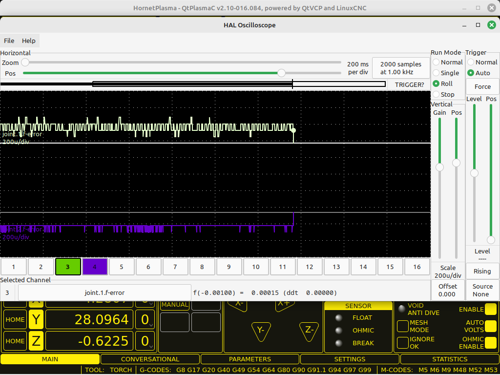
The gantry isn't skewed or in a bind. It is like that even with the motor/gearboxes disengaged from the gear rack.
I noticed while at idle the f error for the dual gantry joints are equal but opposite values. Is that normal?
The gantry isn't skewed or in a bind. It is like that even with the motor/gearboxes disengaged from the gear rack.
- retrofitcenter
01 Oct 2026 20:10
New LinuxCNC Multi-Channel System – Looking for Testers & Feedback was created by retrofitcenter
Hi everyone,I’ve been working on a new multi-channel extension for LinuxCNC, mainly targeting complex turning/milling machines such as INDEX, Gildemeister, multi-spindle lathes and other machines with several independent machining units.The goal is to bring LinuxCNC much closer to the functionality normally found on industrial controls such as Siemens SINUMERIK, especially for machines with multiple turrets, spindles and synchronized machining processes.Main featuresMultiple CNC channelsThe system can run multiple independent machining channels simultaneously. The architecture is not limited to just two channels and is designed to support a very large number of channels, depending mainly on the hardware and machine configuration.Each channel can execute its own NC program independently.Example:
Dynamic axis assignmentAxes are not permanently tied to one channel.An axis can be transferred from one machining channel to another during operation.For example:
This makes it possible to handle machines where several machining units need temporary access to the same spindle or axis.Channel synchronizationThe system includes synchronization functions similar to those used on industrial multi-channel controls.Channels can wait for each other or synchronize at defined points inside their NC programs.Typical applications are:
Code:
Channel 1 → Turret 1 / Main spindle
Channel 2 → Turret 2 / Sub spindle
Channel 3 → Milling unit
Channel 4 → Additional machining unit
...
Code:
Channel 1:
X1 Z1 C1
Channel 2:
X2 Z2 C2
Transfer C1 →
Channel 2:
X2 Z2 C2 C1
- part transfer between main and sub spindle
- synchronized machining
- waiting for another turret
- synchronized spindle operations
- coordinated tool changes
- machining sequences involving several channels
- cylindrical surface machining
- face machining
- C-axis milling
- turning/milling combinations
- complete machine geometry
- tools
- workpiece
- fixtures
- spindles
- turrets
- axis movements
- tool and machine
- tool and chuck
- tool and fixture
- turret and spindle
- machine components
- workpiece and machine
- tool geometry
- tool offsets
- sister tools
- tool life monitoring
- remaining tool life
- automatic replacement with sister tools
- tool status
- tool usage tracking
- INDEX machines
- Gildemeister / DMG machines
- multi-spindle machines
- dual-turret lathes
- main/sub-spindle machines
- complex LinuxCNC configurations
Time to create page: 0.255 seconds