Control cabinet\box rebuild
- BeagleBrainz
-
 Topic Author
- Visitor
-

16 Dec 2020 01:29 - 16 Dec 2020 01:33 #192092
by BeagleBrainz
Replied by BeagleBrainz on topic Control cabinet\box rebuild
Things move slow.
1000 more things to do.
But just a quick update.
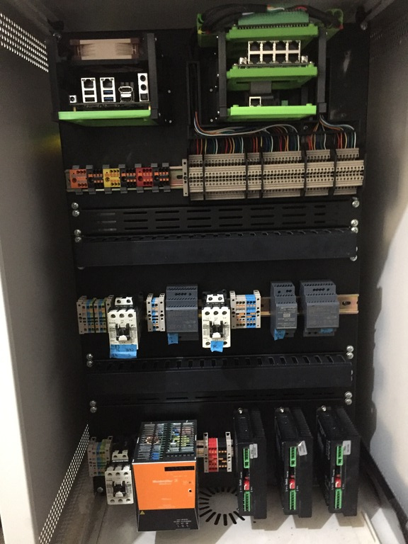
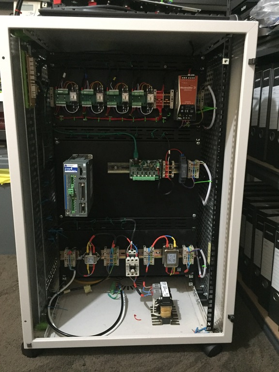
This is the "A" side (aka rear), Odroid, MESA cards & Stepper drivers.
The "B" side (aka front)has the driver for the servo motor spindle, and some control gubbins to turn power on and off.
All panels and uprights to be stripped of powder coating and gold passivated plated. Vents will need some sort of filter material to prevent chip, spiders and snakes getting in. Cooling needs sorting as well.
Would of liked more space but it is what it is.
1000 more things to do.
But just a quick update.
This is the "A" side (aka rear), Odroid, MESA cards & Stepper drivers.
The "B" side (aka front)has the driver for the servo motor spindle, and some control gubbins to turn power on and off.
All panels and uprights to be stripped of powder coating and gold passivated plated. Vents will need some sort of filter material to prevent chip, spiders and snakes getting in. Cooling needs sorting as well.
Would of liked more space but it is what it is.
Last edit: 16 Dec 2020 01:33 by BeagleBrainz.
Please Log in or Create an account to join the conversation.
- johnmc1
- Offline
- Senior Member
-

Less
More
- Posts: 78
- Thank you received: 21
16 Dec 2020 10:24 #192116
by johnmc1
Replied by johnmc1 on topic Control cabinet\box rebuild
Very compact well done
The wiring layout will be interesting to see.")
cheers john
The wiring layout will be interesting to see.
cheers john
Please Log in or Create an account to join the conversation.
- BeagleBrainz
-
Topic Author
- Visitor
-
09 Apr 2021 03:34 - 09 Apr 2021 03:37 #205392
by BeagleBrainz
Replied by BeagleBrainz on topic Control cabinet\box rebuild
Bit of progress.
Not the final product but getting there. Just spent the last couple of days running the control wiring through PET Expandable Braided Cable Sleeve. Was going to colour said sleeving but at $AUD 12.00 per 3m length and at least 8 colours wanted was looking at bit expensive. So black it was from my local electronics store. The pcb in the top left corner of the first picture is the board that will allow me to plug & unplug the front switches & indicator lights. Also added some short lengths of cable tray to give me something to mount the cable tie clips to.
Each PSU group is powered by a separate contactor, which is in turned controlled via a 24v relay that is latched on by a momentary push button. A simple PCB takes care of the circuit for each relay, with diodes for back emf. Saves on mistakes whilst wiring.
So basically if I lose power the machine doesn't come back on by itself.
Group 1 15v for the Odroid H2+
Group 2 5v & 24v for the Mesa logic & VField and a separate 24v for the 7i83
Group 3 48v for the stepper motors
Group 4 Control for the mains for the DYN4 Driver
Fear not all mains will not be left in this state. Line reactor still needs securing to cabinet.
Apart form the mains to the servo, all mains have been kept on on side & all control wiring have been kept on the opposite side.
Attachments:
Last edit: 09 Apr 2021 03:37 by BeagleBrainz.
Please Log in or Create an account to join the conversation.
Time to create page: 0.376 seconds