Yaskawa RP-Y01-2ZI pendant with 7i73
- radar_macgyver
- Offline
- New Member
-

Less
More
- Posts: 10
- Thank you received: 8
27 Nov 2022 19:25 #257755
by radar_macgyver
Yaskawa RP-Y01-2ZI pendant with 7i73 was created by radar_macgyver
Hello all,
I wanted to add a pendant with an MPG to my LinuxCNC setup. After failing to get a USB pendant working to my satisfaction, I bought a 7i73. While looking up suitable keypads to use with it and an enclosure to put it all in, I found that the folks over at CNC4PC had a Yaskawa pendant with a Pokeys board:
www.cnc4pc.com/mpg14-yaskawa-pendant.html
Some digging on ebay found the following seller, who still has a few pendants for sale:
www.ebay.com/itm/143191583159
I ordered one, and found that it uses a separate board for the control electronics (separate from the keypad), so it's easy to replace. The keypad is a 6x8 matrix, and uses diodes per key to support N key rollover. The keys themselves are high-quality NKK parts, not a membrane construction. Each key also has an LED, driven in a matrix form by a transistor drive circuit. The display on board is a 4x20 HD44780 compatible, with all sixteen pins brought out to a 16-pin ribbon. The e-stop is a normally-closed switch, with two separate contacts. There are three rotary switches, for axis select, SRO and FRO. The axis select is a 1-of-5 switch, with the common wired to 5V. The SRO and FRO are 5-bit encoders, with gray-coded parallel outputs and the common wired to 5V. The encoder is the usual 100-step quadrature MPG found everywhere. The SRO, FRO, axis select and MPG are wired together with a harness to a 30-pin ribbon.
I designed a PCB to adapt the 7i73 to drive the keypad. With the 7i73 in 8x8 keypad LCD mode, there are 16 digital inputs, which I connected to the SRO, FRO, axis select, MPG and e-stop. Since my machine only has three axes, I did not wire the '4' and '5' positions of the axis selector. OUT0 from the 7i73 is used to drive the LCD's backlight. The 'CNC Alarm' LED is separately wired, so I have it driven by the FAULT output of the 7i73.
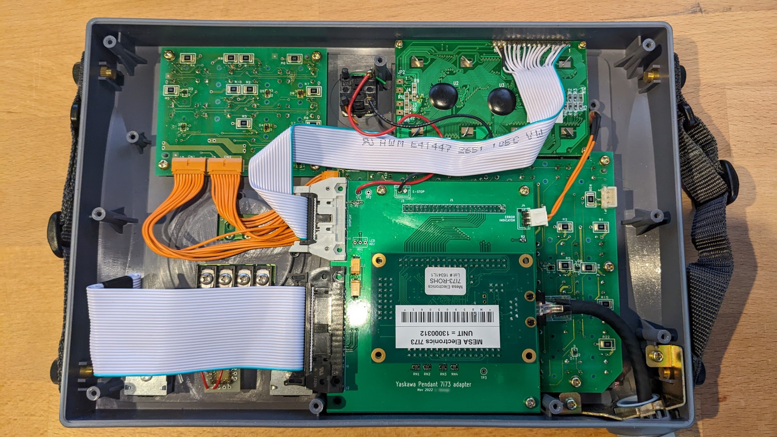
Here is the inside view of the pendant with my adapter board and 7i73. One can see the existing wiring with the gray ribbon cables (I designed the board to not require those cables to be modified).
My board has a couple of goofs:
1. The polarity of the diodes in the key matrix was such that the row drivers from the 7i73 would not work. This is because the 7i73 uses open-collector outputs for the row drive, and depends on an external pull-up. I had thought the 7i73 would actively drive the row outputs. The fix for me was to replace all the diodes on the keypad with reverse-polarity types. The original diodes were common-cathode SC-70 dual diodes, I had a bunch of common-anode diodes in the same package, so I replaced them and it worked ok. I also revised the board to exchange the row and column drivers, so the diodes should not need to be modified.
2. I had wired all eight row drivers to the keypad. It turns out that rows 6 and 7 are grounded on the connector, so I had to cut the traces.
3. The second connector to the 7i73 had a couple of pins connected to ground that should have been connected to +5V. I worked around this by removing the corresponding pins from the connector.
4. The connector for the alarm indicator was a bit too far 'south', the wire was stretched tight as you can see in the picture above.
5. While the digital inputs all have pull-downs, one end of the e-stop switch is grounded. Fixed in the v2 board by connecting to +5V.
I've fixed the goofs above and have included the KiCAD project with schematic and board file, if anyone would like to replicate it.
Here's a picture of the completed unit:

The original pendant came with a cable with a multi-pin round connector on the end. The entry into the pendant is through a strain-relief grommet. I replaced this with a coiled CAT5e cable from Amazon:
www.amazon.com/dp/B082PHY38G
The cable is quite nice, it has a TPE jacket and seems quite sturdy. Had to cut off one of the RJ45 connectors before it would pass through the grommet, though.
One drawback of the design is that the LEDs are not driven. The LED row/column pins are broken out to the J1 connector (pins 27-39). I connected the rows to the same signals as the keyboard rows via some 1k resistors, and the columns to the OUT1-OUT5 signals. However, without a firmware update, the 7i73 won't be able to drive the LEDs. The original board had +24V available, so the LEDs have correspondingly large (2.2k) dropper resistors. With only 5V from the 7i73, those resistors would need to be replaced with 470 ohm parts.
Another issue is that the digital inputs all have 1k pull-down resistors. This was done to avoid modifying the original pendant's wire harness, where the SRO, FRO and axis selector switches are wired to +5V. These pull-downs conflict with the 4.7k pull-up resistors on the 7i73. Ideally, they should be removed, though they seem to work OK even with both resistors in place.
On the configuration side, I had struggled a fair bit with HAL logic before I stumbled across the panelui component which greatly simplifies the use of a keypad. However, I did find some issues with panelui, possibly because I'm not using it correctly:
1. Errors in the .ini file result in a Python exception which doesn't tell me where in the .ini file the error occured but rather the line number in Python source file.
2. The built-in commands available, such as mist coolant on/off do not take into account the current state of the mist coolant from the UI. So for example if I check the mist coolant box in Axis, then push the corresponding keypad button, nothing happens. If I push it again, then the coolant is turned off. I believe this is because panelui is maintaining its own internal state for the coolant, rather than reading it from halui.
3. The 'feed hold' command doesn't seem to do anything.
I also came across a bug in the lcd module, or at least in its documentation, which states that sending a 0x7F will output a left arrow. However, the 7i73 seems to treat this as an ASCII 'DEL', and removes a character instead. Sending a 0x7E outputs a right arrow, as expected. My workaround is to replace the left and right arrows with '<' and '>' respectively.
Anyway, thank you to all the LinuxCNC contributors who did all the hard work so I could just plug some stuff in! Let me know if there's more info I can provide if anyone else would like to try this.
I wanted to add a pendant with an MPG to my LinuxCNC setup. After failing to get a USB pendant working to my satisfaction, I bought a 7i73. While looking up suitable keypads to use with it and an enclosure to put it all in, I found that the folks over at CNC4PC had a Yaskawa pendant with a Pokeys board:
www.cnc4pc.com/mpg14-yaskawa-pendant.html
Some digging on ebay found the following seller, who still has a few pendants for sale:
www.ebay.com/itm/143191583159
I ordered one, and found that it uses a separate board for the control electronics (separate from the keypad), so it's easy to replace. The keypad is a 6x8 matrix, and uses diodes per key to support N key rollover. The keys themselves are high-quality NKK parts, not a membrane construction. Each key also has an LED, driven in a matrix form by a transistor drive circuit. The display on board is a 4x20 HD44780 compatible, with all sixteen pins brought out to a 16-pin ribbon. The e-stop is a normally-closed switch, with two separate contacts. There are three rotary switches, for axis select, SRO and FRO. The axis select is a 1-of-5 switch, with the common wired to 5V. The SRO and FRO are 5-bit encoders, with gray-coded parallel outputs and the common wired to 5V. The encoder is the usual 100-step quadrature MPG found everywhere. The SRO, FRO, axis select and MPG are wired together with a harness to a 30-pin ribbon.
I designed a PCB to adapt the 7i73 to drive the keypad. With the 7i73 in 8x8 keypad LCD mode, there are 16 digital inputs, which I connected to the SRO, FRO, axis select, MPG and e-stop. Since my machine only has three axes, I did not wire the '4' and '5' positions of the axis selector. OUT0 from the 7i73 is used to drive the LCD's backlight. The 'CNC Alarm' LED is separately wired, so I have it driven by the FAULT output of the 7i73.
Here is the inside view of the pendant with my adapter board and 7i73. One can see the existing wiring with the gray ribbon cables (I designed the board to not require those cables to be modified).
My board has a couple of goofs:
1. The polarity of the diodes in the key matrix was such that the row drivers from the 7i73 would not work. This is because the 7i73 uses open-collector outputs for the row drive, and depends on an external pull-up. I had thought the 7i73 would actively drive the row outputs. The fix for me was to replace all the diodes on the keypad with reverse-polarity types. The original diodes were common-cathode SC-70 dual diodes, I had a bunch of common-anode diodes in the same package, so I replaced them and it worked ok. I also revised the board to exchange the row and column drivers, so the diodes should not need to be modified.
2. I had wired all eight row drivers to the keypad. It turns out that rows 6 and 7 are grounded on the connector, so I had to cut the traces.
3. The second connector to the 7i73 had a couple of pins connected to ground that should have been connected to +5V. I worked around this by removing the corresponding pins from the connector.
4. The connector for the alarm indicator was a bit too far 'south', the wire was stretched tight as you can see in the picture above.
5. While the digital inputs all have pull-downs, one end of the e-stop switch is grounded. Fixed in the v2 board by connecting to +5V.
I've fixed the goofs above and have included the KiCAD project with schematic and board file, if anyone would like to replicate it.
Here's a picture of the completed unit:
The original pendant came with a cable with a multi-pin round connector on the end. The entry into the pendant is through a strain-relief grommet. I replaced this with a coiled CAT5e cable from Amazon:
www.amazon.com/dp/B082PHY38G
The cable is quite nice, it has a TPE jacket and seems quite sturdy. Had to cut off one of the RJ45 connectors before it would pass through the grommet, though.
One drawback of the design is that the LEDs are not driven. The LED row/column pins are broken out to the J1 connector (pins 27-39). I connected the rows to the same signals as the keyboard rows via some 1k resistors, and the columns to the OUT1-OUT5 signals. However, without a firmware update, the 7i73 won't be able to drive the LEDs. The original board had +24V available, so the LEDs have correspondingly large (2.2k) dropper resistors. With only 5V from the 7i73, those resistors would need to be replaced with 470 ohm parts.
Another issue is that the digital inputs all have 1k pull-down resistors. This was done to avoid modifying the original pendant's wire harness, where the SRO, FRO and axis selector switches are wired to +5V. These pull-downs conflict with the 4.7k pull-up resistors on the 7i73. Ideally, they should be removed, though they seem to work OK even with both resistors in place.
On the configuration side, I had struggled a fair bit with HAL logic before I stumbled across the panelui component which greatly simplifies the use of a keypad. However, I did find some issues with panelui, possibly because I'm not using it correctly:
1. Errors in the .ini file result in a Python exception which doesn't tell me where in the .ini file the error occured but rather the line number in Python source file.
2. The built-in commands available, such as mist coolant on/off do not take into account the current state of the mist coolant from the UI. So for example if I check the mist coolant box in Axis, then push the corresponding keypad button, nothing happens. If I push it again, then the coolant is turned off. I believe this is because panelui is maintaining its own internal state for the coolant, rather than reading it from halui.
3. The 'feed hold' command doesn't seem to do anything.
I also came across a bug in the lcd module, or at least in its documentation, which states that sending a 0x7F will output a left arrow. However, the 7i73 seems to treat this as an ASCII 'DEL', and removes a character instead. Sending a 0x7E outputs a right arrow, as expected. My workaround is to replace the left and right arrows with '<' and '>' respectively.
Anyway, thank you to all the LinuxCNC contributors who did all the hard work so I could just plug some stuff in! Let me know if there's more info I can provide if anyone else would like to try this.
The following user(s) said Thank You: andypugh, tommylight, HansU, JT, Malcolm
Please Log in or Create an account to join the conversation.
- HansU
-

- Offline
- Platinum Member
-

Less
More
- Posts: 723
- Thank you received: 217
14 Dec 2022 12:32 #259455
by HansU
Did you report that bug?
Replied by HansU on topic Yaskawa RP-Y01-2ZI pendant with 7i73
I also came across a bug in the lcd module, or at least in its documentation, which states that sending a 0x7F will output a left arrow. However, the 7i73 seems to treat this as an ASCII 'DEL', and removes a character instead. Sending a 0x7E outputs a right arrow, as expected. My workaround is to replace the left and right arrows with '<' and '>' respectively.
Did you report that bug?
Please Log in or Create an account to join the conversation.
- PCW
-

- Offline
- Moderator
-

Less
More
- Posts: 17985
- Thank you received: 5278
14 Dec 2022 16:22 #259472
by PCW
Replied by PCW on topic Yaskawa RP-Y01-2ZI pendant with 7i73
Did you try 0xFF for the Left Arrow? (0x7F is ASCII DEL)
Please Log in or Create an account to join the conversation.
- MikeRomill
- Offline
- New Member
-
Less
More
- Posts: 3
- Thank you received: 0
06 Jan 2023 17:39 - 11 Jan 2023 20:49 #261108
by MikeRomill
Replied by MikeRomill on topic Yaskawa RP-Y01-2ZI pendant with 7i73
Hello Radar,After looking at your post and the great work you’ve done on your pendant, I’ve decided that I am going to put one together for myself. I have already ordered a pendant and a 7i73.I’ll be connecting the pendant to my RPI4-7c80 controller. It is set up for 5 axes (currently only using 4), so I’ll need to modify your board design slightly.I’m studying your KiCad files and wiring in a 4th axis seems like a pretty easy modification, but I think that in order to not lose any other functionality, I might have wire something else directly to the 7c80 (probably EStop). Thank you for sharing all of your hard work and inspiring me to attempt this. If you would care to share a little more, I would love to see your configuration files so I can see what kind of changes I will need to make to mine.Thanks again,JJP
Last edit: 11 Jan 2023 20:49 by MikeRomill. Reason: Removed picture
Please Log in or Create an account to join the conversation.
- radar_macgyver
- Offline
- New Member
-
Less
More
- Posts: 10
- Thank you received: 8
25 Mar 2023 23:27 #267511
by radar_macgyver
Replied by radar_macgyver on topic Yaskawa RP-Y01-2ZI pendant with 7i73
Hi folks, sorry I don't seem to have working notifications on this forum so I didn't see your responses.
@HansU: sorry I did not report the bug except on here - not really sure how one does that.
@PCW: I did try 0xFF, that puts up a solid block, not a left arrow. Since I posted the previous message, I've updated to LinuxCNC 2.9.0 pre0 and kernel 5.15.27, I tried again with 0xFF and it still shows a solid block. The HD44780 font mapping normally uses 0x7F for a left arrow, so I'm guessing that the 7i73 firmware treats 0x7F as a DEL and doesn't display it. The HD44780 font also defines 0xFF as a solid block.
@Mike: I've attached my config, warts and all. It's quite ugly since it's my first experience with LinuxCNC and I never did a clean rewrite. By the time I added the pendant, I learned enough to break out that part into separate hal files, it's under 'pendant.hal' (deals with the axis, FRO and SRO selectors), 'mpg.hal' (the MPG), 'lcd.hal' (the display, mapping various arguments) and keypad.hal (the softkeys, using panelui). Panelui.ini defines the mapping of various keys to their respective functions. I use the "F1-F4" keys under the display to switch pages on the LCD, but I've only defined one useful page.
The LCD format string I chose indicates if each axis is homed using an asterisk and an arrow showing the currently selected axis (with the axis selector). The spindle direction is shown with a "<" or ">" for CW or CCW. Both commanded and measured spindle RPM are shown, along with an asterisk for an "at speed" indicator.
You may need to tweak the ilowpass settings in mpg.hal to limit the commanded acceleration when using the mpg. On my machine, I could induce a following error without the ilowpass, unless I moved the mpg very slowly.
I'm using a 7C81 with an RPi. If you want to use the e-stop, you can use a custom cable to bring the signals to the 7C80 in addition to the RJ45 for the serial bus. The estop switch in the pendant has two parallel NC contacts. Adding the fourth axis can use IN15 (in place of estop).
The following user(s) said Thank You: MikeRomill, Malcolm
Please Log in or Create an account to join the conversation.
- MikeRomill
- Offline
- New Member
-
Less
More
- Posts: 3
- Thank you received: 0
26 Mar 2023 14:36 #267529
by MikeRomill
Replied by MikeRomill on topic Yaskawa RP-Y01-2ZI pendant with 7i73
Thank you for the tips and for sharing your files. I hope to get back to that project soon. When I do, I’ll report on my progress.
Please Log in or Create an account to join the conversation.
- COFHAL
- Offline
- Platinum Member
-
Less
More
- Posts: 457
- Thank you received: 62
02 Nov 2023 16:13 #284344
by COFHAL
Replied by COFHAL on topic Yaskawa RP-Y01-2ZI pendant with 7i73
From what I understand, the 7i73 only works with 4x20 LCDs. My question is if it is possible to use it with a 4x40 LCD, such as the one manufactured by AMPIRE model AC404-A.
Please Log in or Create an account to join the conversation.
- PCW
-
- Offline
- Moderator
-
Less
More
- Posts: 17985
- Thank you received: 5278
02 Nov 2023 18:18 - 02 Nov 2023 19:10 #284353
by PCW
Replied by PCW on topic Yaskawa RP-Y01-2ZI pendant with 7i73
The 7I73 can work with different LCD sizes, it requires changing the default
LCD size EEPROM setup parameter: nvdisplaymode
LCD size EEPROM setup parameter: nvdisplaymode
Last edit: 02 Nov 2023 19:10 by PCW.
The following user(s) said Thank You: COFHAL
Please Log in or Create an account to join the conversation.
- COFHAL
- Offline
- Platinum Member
-
Less
More
- Posts: 457
- Thank you received: 62
02 Nov 2023 23:18 #284398
by COFHAL
Replied by COFHAL on topic Yaskawa RP-Y01-2ZI pendant with 7i73
Thanks for your reply. How can this be done in practice?
Please Log in or Create an account to join the conversation.
- PCW
-
- Offline
- Moderator
-
Less
More
- Posts: 17985
- Thank you received: 5278
03 Nov 2023 00:51 #284405
by PCW
Replied by PCW on topic Yaskawa RP-Y01-2ZI pendant with 7i73
Well its not guaranteed (I dont think a display that size has been tried before)
but setting nvdispmode to 1064 = 4x40 would be a start.
You would do this by having this line:
setp nvdispmode 1064
In your hal file, starting linuxcnc, exiting linuxcnc and commenting
out the line in the hal file so it's not run again (the setting is non-volatile)
If you want to return it to the default 20x4 you would write 1044
( The high byte of dispmode is the number of lines, the low byte
is the number of columns )
The following user(s) said Thank You: COFHAL
Please Log in or Create an account to join the conversation.
Time to create page: 0.298 seconds